Pulsed ion trap transference tube with carrier gas and transference gas

An ion trap migration tube and migration gas technology, applied in the field of ion migration tubes, can solve the problems of inability to quickly switch detection modes, low detection accuracy, and high sample ion loss rate, so as to overcome the drift of characteristic ion peaks, simplify the system structure, The effect of improving system sensitivity

Active Publication Date: 2014-10-08
GUANGDONG NANHAI ETETB TECH CO LTD
View PDF7 Cites 3 Cited by
  • Summary
  • Abstract
  • Description
  • Claims
  • Application Information

AI Technical Summary

Problems solved by technology

[0003] The purpose of the present invention is to provide a pulsed ion trap transfer tube with carrier gas and transfer gas to simultaneously solve the technical problems of low detection accuracy, high sample ion loss rate and inability to quickly switch detection modes in the above-mentioned traditional ion transfer tube.

Method used


Image

  • Pulsed ion trap transference tube with carrier gas and transference gas
  • Pulsed ion trap transference tube with carrier gas and transference gas

Examples


Embodiment Construction

[0013] In order to make the object, technical solution and advantages of the present invention more clear and definite, the present invention will be further described below with reference to the accompanying drawings and examples.

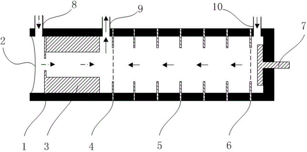
[0014] Such as figure 1 As shown, a pulsed ion trap migration tube with carrier gas and migration gas provided by the present invention includes: an insulating tube 1, a diaphragm 2, an ionization source 3, a single gate ion gate 4, a migration ring 5, a shielding grid 6 and a Faraday Disk 7.

[0015] The insulating tube 1 constitutes the outer wall of the migration tube in the present invention, and one end of the insulating tube 1 is set as an open type, and the other end is set as a closed type. In the inner cavity of the insulating tube 1, from the open end to the closed end, a diaphragm 2, an ionization source 3, a single gate ion gate 4, a transfer ring 5, a shielding grid 6 and a Faraday disk 7 are arranged in sequence, wherein the diaphra...


PUM


Abstract

The invention provides a pulsed ion trap transference tube with carrier gas and transference gas. The pulsed ion trap transference tube comprises an insulating tube, wherein one end of the insulating tube is open, and the other end of the insulating tube is closed. The pulsed ion trap transference tube further comprises a diaphragm, an ionization source, a single-grid ion gate, a transference ring, a shielding grid and a Faraday disk, wherein the diaphragm, the ionization source, the single-grid ion gate, the transference ring, the shielding grid and the Faraday disk are sequentially arranged in an inner cavity of the insulating tube in the direction from the open end to the closed end. The position, between the diaphragm and the ionization source, of the side wall of the insulating tube is provided with a carrier gas inlet. The position, between the ionization source and the single-grid ion gate, of the side wall of the insulating tube is provided with an exhaust outlet. The position, between the shielding grid and the Faraday disk, of the side wall of the insulating tube is provided with a transference gas inlet. By applying excitation electric fields of different attributes to an iron trap, cooperative detection of positive and negative ions can be achieved. By the adoption of the mode that the carrier gas and the transference gas are supplied separately, the phenomenon that characteristic ion peaks drift due to the overhigh molecular concentration of a sample is eliminated, and meanwhile the technical problems that a traditional transference tube product is high in ion loss rate, poor in map stability, long in analysis time and the like are solved.

Description

technical field [0001] The invention relates to an ion transfer tube, in particular to a pulse ion trap transfer tube with carrier gas and transfer gas. Background technique [0002] Ion mobility spectrometer is an efficient and sensitive trace detection equipment, which can be used for rapid detection of drugs and explosives. Among them, the transfer tube is the core component of the ion mobility spectrometer. There are two types of traditional transfer tubes. One is the single gas path ion trap transfer tube (see US Patent 5200614). The formation and storage of product ions are completed in the ion trap, with The product ion formation efficiency is high, the loss rate is low, and the detection mode can be quickly switched. However, when the concentration of the detected sample molecules is high, limited by the ionization capacity of the ion trap, a large number of unionized sample molecules enter the migration area with the carrier gas. , causing the characteristic ion pe...

Claims


Application Information

Patent Timeline
Patent Type & Authority Applications(China)
IPC IPC(8): H01J49/04H01J49/00G01N27/62G01N27/622
Inventor 郭会勇周虎
Owner GUANGDONG NANHAI ETETB TECH CO LTD
Why Eureka
Try Eureka