Photoelectric rocker and coordinate origin determination method thereof

A photoelectric and photoelectric mouse technology, applied in the field of joysticks, can solve the problems of rising costs and limited accuracy, and achieve the effect of low cost

Active Publication Date: 2013-01-09
SOUTH CHINA UNIV OF TECH
View PDF4 Cites 0 Cited by
  • Summary
  • Abstract
  • Description
  • Claims
  • Application Information

AI Technical Summary

Problems solved by technology

With the improvement of the precision of the photoelectric encoder disc, the cost will increase significantly, thus limiting the further improvement of the precision

Method used


Image

  • Photoelectric rocker and coordinate origin determination method thereof
  • Photoelectric rocker and coordinate origin determination method thereof
  • Photoelectric rocker and coordinate origin determination method thereof

Examples


Embodiment

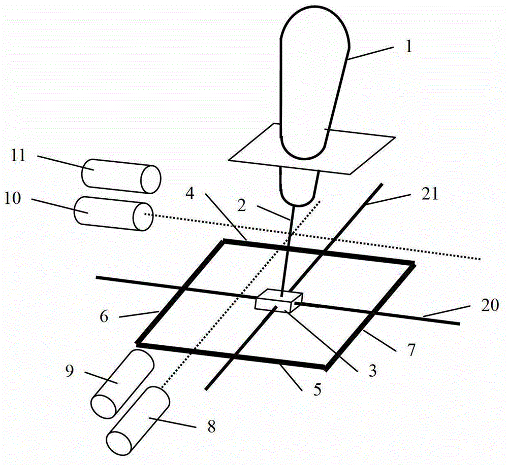
[0031] Such as figure 1 As shown, the photoelectric joystick of this embodiment includes a joystick body 1, a telescopic connecting rod 2, a photoelectric mouse module 3, guide rail shafts 4~7, an X-axis guide shaft 20, a Y-axis guide shaft 21, a processor, an X-axis Axis laser transmitter 8, X-axis laser receiver 9, Y-axis laser transmitter 10, Y-axis laser receiver 11; the rocker body 1 is connected with the photoelectric mouse module 3 through the telescopic connecting rod 2; the The photoelectric mouse module 3 is electrically connected with the processor.

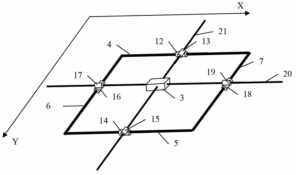
[0032] Such as figure 2 As shown, the Cartesian coordinate system of the present invention takes the direction parallel to the guide rail axis 4 as the X-axis direction, and the direction parallel to the guide rail axis 6 as the Y-axis direction. The guide rail shafts 4 to 7 are connected end to end to form a rectangle; the guide rail shaft 4 is provided with a guide rail shaft slider 12 sliding along the guide rail...


PUM


Abstract

The invention discloses a photoelectric rocker. The photoelectric rocker comprises a rocker rod body, a telescopic connecting rod, an optical mouse module, four guide rail shafts, an X-axis guiding shaft, a Y-axis guiding shaft, a processor, an X-axis laser emitter, an X-axis laser receiver, a Y-axis laser emitter and a Y-axis laser receiver. According to the rocker, shake of the rocker rod body is converted into plane motion of the optical mouse module by restriction of the guide rail shafts and the guiding shafts, coordinate variation is acquired by acquiring an optical mouse chip signal by the processor, digital measurement is realized, the shortcoming of low accuracy of the conventional two-dimensional potentiometer-type rocker is overcome, and the shortcoming that cost is increased obviously along with the improving of the accuracy of the conventional photoelectric-coded-disk-type rocker is overcome.

Description

technical field [0001] The invention relates to a rocker, in particular to a photoelectric rocker and a method for determining its coordinate origin. Background technique [0002] The existing rocker mainly uses the realization method of the two-dimensional potentiometer. When the rocker is shaken, the resistance value of the potentiometer changes, and the shaking amount of the rocker is determined by the resistance value. The current potentiometer rocker is prone to drift due to the influence of the environment such as temperature, the accuracy is not high, and there are problems such as mechanical wear of the contacts. [0003] The patent with the application number CN96102685.5 discloses a photoelectric digital rocker, which applies the principle of the photoelectric encoder disc, converts the shaking amount of the rocker into the rotation amount of the photoelectric encoder disc in two dimensions, and detects the rotation amount And reverse conversion to get the rocking...

Claims


Application Information

Patent Timeline
Patent Type & Authority Applications(China)
IPC IPC(8): G06F3/0354
Inventor 陈暑生陈安黄旭东胡跃明
Owner SOUTH CHINA UNIV OF TECH
Why Eureka
Try Eureka