Pressure backfill type elastic buried pipe construction method

A construction method, penstock technology, applied in filling, pipeline laying and maintenance, pipes/pipe joints/pipe fittings, etc., can solve problems affecting ground vegetation and normal use, complex stress conditions, and large environmental damage, etc., to achieve The effect of improving design and construction technology level, fast construction progress and shortening excavation time

Active Publication Date: 2014-10-08
SINOHYDRO BEREAU 10 CO LTD
View PDF4 Cites 14 Cited by
  • Summary
  • Abstract
  • Description
  • Claims
  • Application Information

AI Technical Summary

Problems solved by technology

[0003] In the existing technology, in order to realize the pipeline fixing and construction, the following two methods are commonly used: one is the underground buried pressure pipeline, which means that the pipeline is buried in the ground, and the steel pipe is surrounded by a layer of reinforced concrete and surrounding rock. Although the pipeline is fixed underground, the construction is complicated, the adaptability is poor, the cost is high, and the damage to the environment is great; the second is the open-air penstock, which means that the penstock is exposed on the surface and is fixed by the township and buttresses , although this method can reduce the damage to the environment, the open-air type is easy to damage and affects the vegetation and normal use of the ground, which also has major defects
[0004] However, some pipelines also need to match larger pressures, and the stress situation is more complicated, which puts forward higher requirements for pipelines and pipeline supports.

Method used


Image

  • Pressure backfill type elastic buried pipe construction method
  • Pressure backfill type elastic buried pipe construction method
  • Pressure backfill type elastic buried pipe construction method

Examples


Embodiment Construction

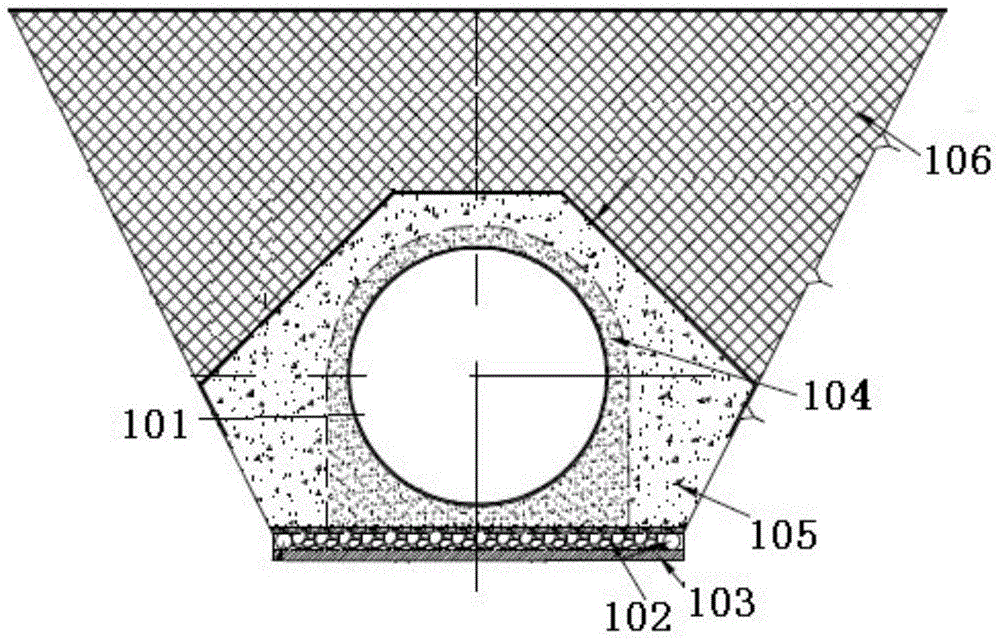
[0034] see figure 1 , shows a schematic cross-sectional view of the pressure backfill elastic buried pipe construction method of the present invention.

[0035] In order to avoid the impact on the environment and reduce the steel pipe outsourcing concrete and buttress structures as much as possible, the present invention selects relatively shallow pipe grooves and elastic buried pipes, and adopts the following steps:

[0036] Step 1: pipe groove excavation and support

[0037] (1) For earthwork excavation, measure the ground line required for excavation, and then directly excavate through the trench excavation method after removing vegetation, and dig out soil and gravel materials. For slope stability and engineering construction, an intercepting ditch parallel to the pipe groove is arranged outside 2m from both sides of the excavation line. Preferably, the size of the intercepting ditch is 50cm×50cm;

[0038] (2) Stonework excavation is carried out by drilling and blasting ...


PUM

PropertyMeasurementUnit
Particle sizeaaaaaaaaaa

Abstract

The invention discloses a pressure backfill type elastic buried pipe construction method. The method includes the first step of pipe groove excavation and supporting, the second step of pressure steel pipe manufacturing, the third step of pressure steel pipe installation, the fourth step of pipeline backfilling, the fifth step of rolling and leveling, wherein the second step contains the procedures of (1) steel pipe blanking, (2) steel pipe plate rolling, (3) longitudinal joint pairing, (4) steel pipe united section welding and (5) surface treatment; compaction and leveling are carried out on backfilled pipe grooves through a rolling machine to complete the whole procedure. According to the pressure backfill type elastic buried pipe construction method, a pressure steel pipe is regarded as a flexible buried pipe structure, backfilling and compaction are conducted on the periphery of the steel pipe through aggregate, the steel pipe is allowed to freely deform in backfill materials to release stress, and therefore the design and construction technological level of hydraulic and hydro-power engineering of China is improved. The method is suitable for environments with rock breakage, thick covering layers and uneven terrain and has broad application prospects.

Description

technical field [0001] The invention relates to the technical field of buried pipe construction, in particular to a pressure backfill elastic buried pipe construction method. Background technique [0002] With the continuous improvement of people's living standards, there are more and more various infrastructures, such as power stations, etc. Although this infrastructure is for human services, in order to realize such infrastructure, it is often necessary to carry out pipeline construction. The required pipelines are used to realize the transportation and transportation of water, lines, etc., but as people gradually pay attention to the environment, they also hope that this kind of infrastructure can reduce the impact on the environment as much as possible. Moreover, in pipeline construction, due to The environment is complex, the terrain is uneven, and the height is uneven, which also puts forward higher and higher requirements for the construction of buried pipes. [0003...

Claims


Application Information

Patent Timeline
IPC IPC(8): F16L1/028E02D17/18
CPCE02D17/18F16L1/038
Inventor 吴方明胡湛军杜学泽喻广平刘仕发王治烘王强
Owner SINOHYDRO BEREAU 10 CO LTD
Why Eureka
Try Eureka