
Axial-flow fan

An axial flow fan and fan technology, applied in the direction of cleaning methods using gas flow, components of pumping devices for elastic fluids, applications, etc., can solve the risk of exacerbating the breakage of the connecting part, affecting the stability of the fan operation, blades Large air resistance and other problems, to achieve the effect of increasing air volume and efficiency, improving power utilization, and ensuring stability

Active Publication Date: 2014-10-08
SUZHOU SAMSUNG ELECTRONICS CO LTD +1
View PDF7 Cites 2 Cited by
  • Summary
  • Abstract
  • Description
  • Claims
  • Application Information

AI Technical Summary

Problems solved by technology

[0005] First: The connecting part between each blade is designed to be formed from the blade and used for blowing air along with the rotation. The connecting part is a thin-walled airfoil structure with a smooth transition from the blade airfoil. It is easy to vibrate, which affects the stability of the fan operation, and the air resistance on the blades will be greater, and the connection part may be easily broken due to force.
[0006] In addition, in order to consider the ease of making molds and the ease of stacking and transporting fans, a plane transition is added to the middle of the connecting part, which further exacerbates the risk of breaking the connecting part
[0007] Second: Since the blade and the connecting part are integrally formed with a thin-walled shape, the connecting part is a relatively flat transition, and the projected area of ​​the connecting part in the center on a plane perpendicular to the fan axis is not much reduced, resulting in The negative effect is the impact on the central wind force, that is, the air outlet efficiency of the connection part is not much improved compared with the traditional axial fan

Method used


Image

  • Axial-flow fan
  • Axial-flow fan
  • Axial-flow fan

Examples


Embodiment Construction

[0030] As shown in the background art, among the existing axial flow fans, for the axial flow fan with hub type, there is no wind outlet effect at the hub, so its air outlet efficiency is affected by the size of the hub area, and the material used for the hub It also increases the production cost of the axial flow fan. For the improvement of this fan, the design of the hub is canceled, and an integrally formed axial flow fan is proposed. Yet the existing hubless axial flow fan, because its joint and the joint in the middle of the fan blade are thin-walled airfoil structures that transition smoothly from the blade, due to the cancellation of the hub, the joint and the smaller rotating shaft The connection strength of the fan is greatly reduced. The thin wing design of this fan makes the fan prone to vibration during rotation, which increases the risk of breaking due to force. Moreover, due to the continuous airfoil-like structure, the wind outlet effect at the center of the fa...


PUM


Abstract

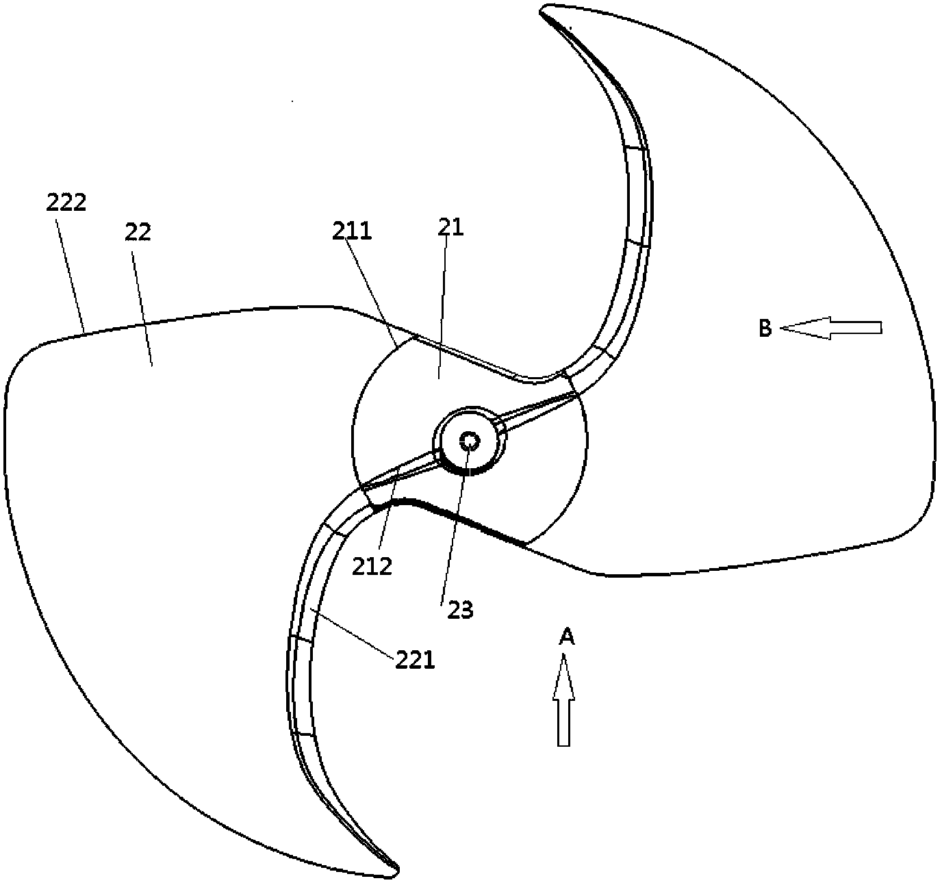
The invention discloses an axial-flow fan which comprises a plurality of blades which are circumferentially arranged apart and a rotary shaft part which is configured in the rotary center of the blades and provided with a shaft hole used for mounting a motor shaft, wherein connecting piece body structures which are used for connecting the root parts of the blades to the rotary shaft part and are connected with one another are arranged at the root parts of the blades; each connecting piece body structure is in a V shape distorted from the air suction side to the air blowing side of the fan, the V-shaped opening part faces to the air blowing side, and the extension line of the V ridge part of the V shape passes through the shaft center of the rotary shaft part and the root part of the front edge of each blade; the blades, the connecting piece body structures and the rotary shaft part are integrated. Therefore, the strength of the connecting piece body structures and the whole fan connecting part is enhanced and the air discharge effect of the central region of the fan is improved.

Description

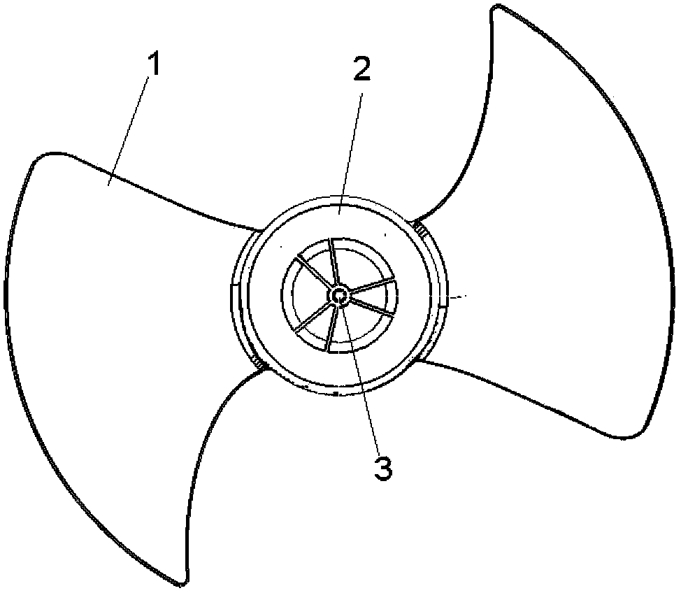
technical field [0001] The present invention relates to an axial flow fan, more specifically, a hubless axial flow fan. Background technique [0002] See figure 1 and figure 2 , figure 1 and figure 2 It depicts a traditional axial flow fan structure, which is basically composed of two parts, fan blade 1 and fan hub 2, fan blade 1 is installed on the side of hub 2 at a certain angle and in a certain way, and the center of hub 2 is the motor Install shaft hole 3. The hub 2 is generally cylindrical, with a large volume and a high amount of material used. The ratio of its diameter to the outer diameter of the fan is called the hub ratio, which generally ranges from 0.3 to 0.4. Restricted by structural design limitations of traditional axial flow fans and fan strength requirements, the hub 2 has always been an indispensable part in the design of axial flow fans (especially injection molded axial flow fans). Because the diameter of the fan hub 2 is too small, the blade can...

Claims


Application Information

Patent Timeline
Patent Type & Authority Applications(China)
IPC IPC(8): F04D29/38
CPCA47L5/362B08B5/04
Inventor 黄华张辉
Owner SUZHOU SAMSUNG ELECTRONICS CO LTD
Learn More