Overall self-propelled hydraulic lining trolley and refitting method thereof
A lining trolley, self-propelled technology, applied in shaft lining, tunnel lining, shaft equipment and other directions, can solve the problems affecting the excavation progress of the tunnel face, increasing the cost of tunnel construction, and increasing the number of lining trolleys, etc. The trolley modification process is simple, the trolley investment is reduced, and the effect of the excavation progress is not affected.
- Summary
- Abstract
- Description
- Claims
- Application Information
AI Technical Summary
Problems solved by technology
Method used
Image
Examples
Embodiment 1
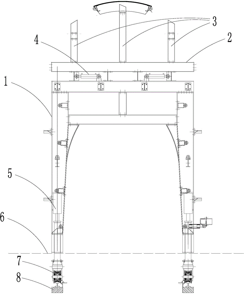
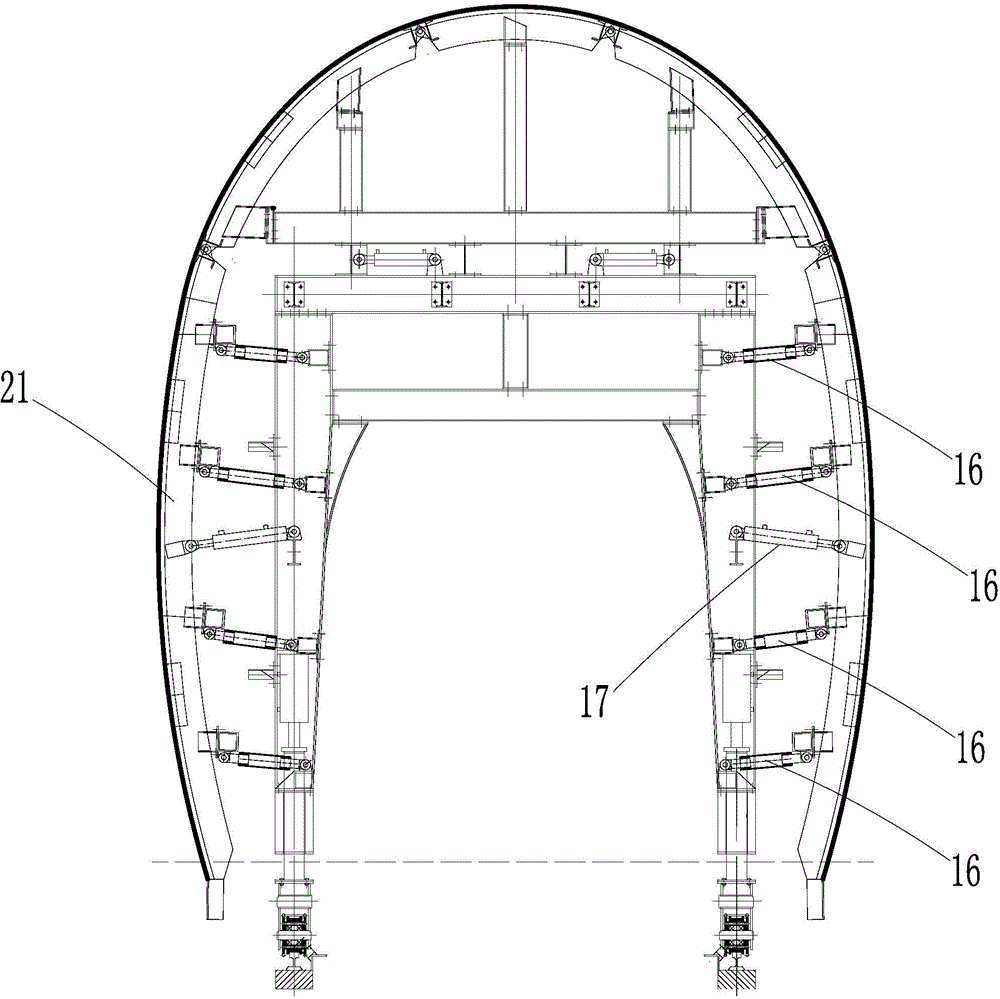
[0031] Such as figure 1 as shown, figure 1 It is a structural schematic diagram of the main frame 1 of the trolley, and the vertical frame 3 and the beam 2 are arranged on the upper end of the main frame 1 of the trolley. figure 2 It is a structural schematic diagram of the section widening value W=50+5cm, combined with figure 2 As shown, the integral self-propelled hydraulic lining trolley of the present invention includes an integral formwork, a trolley main frame 1 supporting the integral formwork, a vertical framework 3 supporting the integral formwork and a beam 2, arched at the left and right sides of the integral formwork The first hinge 13 and the second hinge 11 are arranged respectively at the position of 19-20 degrees; Figure 4 , the mark 18 is the radian of the position of the second hinge 13 .
[0032] Also, combine Figure 4 , the lining trolley of the present invention also includes a vertical adjustment block 19 for adjusting the height of the vertical f...
Embodiment 2
[0042] as attached image 3 Shown is the structural representation of the present invention at section widening value W=30+5cm, and the attached figure 2 The difference is that hydraulic system one 5 and hydraulic system two 4 are used to adjust the trolley to the design elevation and width of the changed section, and the hydraulic cylinder 16 and mechanical screw 17 are used to adjust the distance between the overall formwork and the main frame of the trolley. distance, and replaced the horizontal adjustment block and vertical adjustment block suitable for the changed section, and made full use of the directional rotation function of the hinge to adjust the overall formwork angle of the lining trolley, so that the outer contour radian of the lining trolley formwork is consistent with the designed lining The clear section is consistent, and the trolley is positioned and reinforced after meeting the design size.
Embodiment 3
[0044] as attached Figure 4 Shown is the structural representation of the present invention at section widening value W=10+5cm, and attached figure 2 And attached image 3 The difference is that hydraulic system one 5 and hydraulic system two 4 are used to adjust the trolley to the design elevation and width of the changed section, and the hydraulic cylinder 16 and mechanical screw 17 are used to adjust the distance between the overall formwork and the main frame of the trolley. distance, and replaced the horizontal adjustment block and vertical adjustment block suitable for the changed section, and made full use of the directional rotation function of the hinge to adjust the overall formwork angle of the lining trolley, so that the outer contour radian of the lining trolley formwork is consistent with the designed lining The clear section is consistent, and the trolley is positioned and reinforced after meeting the design size. Figure 4 The angle of the middle mark 18 is...
PUM
 Abstract
Description
Claims
Application Information
 - Generate Ideas
- Intellectual Property
- Life Sciences
- Materials
- Tech Scout
- Unparalleled Data Quality
- Higher Quality Content
- 60% Fewer Hallucinations
Browse by: Latest US Patents, China's latest patents, Technical Efficacy Thesaurus, Application Domain, Technology Topic, Popular Technical Reports.
© 2025 PatSnap. All rights reserved.Legal|Privacy policy|Modern Slavery Act Transparency Statement|Sitemap|About US| Contact US: help@patsnap.com


