
Video cloud monitoring method and system based on Internet

A monitoring system and video cloud technology, applied in CCTV systems, transmission systems, electrical components, etc., can solve the problems of limited distribution, users cannot view monitoring video, single function, etc., and achieve the effect of avoiding line restrictions

Inactive Publication Date: 2014-10-01
山东同方焮通经贸有限公司
View PDF4 Cites 18 Cited by
  • Summary
  • Abstract
  • Description
  • Claims
  • Application Information

AI Technical Summary

Problems solved by technology

However, the widely used traditional video surveillance technology can only play the role of anti-theft and local monitoring and recording, which is far behind the needs of social development.
[0003] The traditional video surveillance system is an analog video surveillance system. The analog video surveillance system is composed of a surveillance terminal and a video wall. In the analog video surveillance system, the front-end camera sends the analog video signal to the matrix surveillance host through a video cable. The monitoring host then transmits the received analog video signal to the TV wall in the main control room for user monitoring, but this monitoring system has obvious defects, such as the distribution of points is limited by the line, the amount of project is large, and the cycle of the project is long. lack of mobility
Single performance, inconvenient to view
not suitable for home use
The current remote video surveillance system refers to a system that can control the pan / tilt / lens and store video surveillance images through standard telephone lines, networks, mobile broadband and ISDN data lines or directly connect to the client, but the current remote video surveillance needs Only when the camera is in the working state and the user logs in to the client can the remote monitoring be realized on the client or the alarm of abnormal monitoring can be received. Meet the monitoring needs of users
At the same time, there are complex system settings, single functions, and low work efficiency, which cannot meet the needs of the current society.

Method used


Image

  • Video cloud monitoring method and system based on Internet
  • Video cloud monitoring method and system based on Internet

Examples


Embodiment Construction

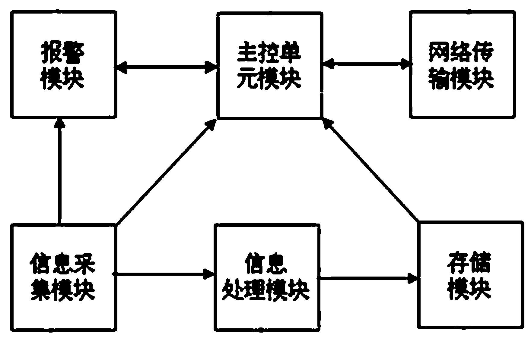
[0022] Attached below figure 1 , attached figure 2 The present invention will be further described.

[0023] This Internet-based video cloud monitoring method comprises the steps:

[0024] (1) Establish a device consisting of an information collection module connected to a CCD image sensor or a CMOS image sensor, an information processing module connected to the information collection module, a storage module connected to the information processing module, and a main control unit module connected to the storage module end, and specify the identification ID of the device end. CCD image sensor or CMOS image sensor is mainly used for image forming. The CCD image sensor is composed of photodiodes arranged two-dimensionally on the monocrystalline silicon and their transmission channels. The photodiodes convert light into charges, and then pass through the conversion circuit. Transmission and output, the image quality of the CCD image sensor is better. CMOS image sensor is a se...


PUM


Abstract

The invention relates to a video cloud monitoring method and system based on the Internet. An equipment side is established and used for identifying IDs, a cloud service platform is established, a client side logs in an account, then is connected to the cloud service platform and sends an instruction for reading monitoring data, and the cloud service platform sends stored monitoring videos corresponding to the equipment side to the client side. The problems that storage capacity is insufficient due to the fact that the equipment side is directly used for storing the monitoring data and related data need to be deleted so that sufficient storage capacity can be provided are solved. Remote monitoring for monitored areas in network coverage areas without influences of time and regions is achieved by means of mobile equipment, and the purpose of remote monitoring is better achieved. The problems that according to a traditional video monitoring system, distribution points of are limited by lines, the work amount of distribution points is large and the project cycle of distribution points is long and lack of mobility are effectively avoided.

Description

technical field [0001] The invention relates to the technical field of video monitoring, in particular to an Internet-based video cloud monitoring method and monitoring system. Background technique [0002] Due to the rapid social and economic development today, the number of single families has increased sharply. According to the "China Family Development Report 2014" issued by the National Health and Family Planning Commission, the number of Chinese families has reached 430 million, ranking first in the world. The family size is becoming smaller and smaller. The average family size 3.02 people. Among family types, the proportion of elderly people living alone is gradually increasing, and single-parent families, DINK families, and intergenerational families are showing rapid growth. The tendency of the floating population to migrate with their families is becoming more and more obvious, and a large number of floating families and left-behind families appear. The focus ...

Claims


Application Information

Patent Timeline
Patent Type & Authority Applications(China)
IPC IPC(8): H04N7/18H04L29/08
Inventor 潘一民
Owner 山东同方焮通经贸有限公司
Learn More