Valley filling circuit

A technology of valley filling circuit and rectification circuit is applied in the field of rectification and filtering to achieve the effects of low cost, small size and low working voltage

Active Publication Date: 2014-10-01
MORNSUN GUANGZHOU SCI & TECH
View PDF9 Cites 3 Cited by
  • Summary
  • Abstract
  • Description
  • Claims
  • Application Information

AI Technical Summary

Problems solved by technology

[0026] In view of this, the present invention aims to solve the deficiencies of existing valley-filling circuits, and provides a valley-filling circuit. When working with a flyback switching power supply, high-voltage capacitors with high cost and large volume are not needed, and the circuit application is simple. The influence of the factor is very small, and it is easy to select the capacity value in the circuit design without compromise

Method used


Image

  • Valley filling circuit
  • Valley filling circuit
  • Valley filling circuit

Examples


no. 1 example

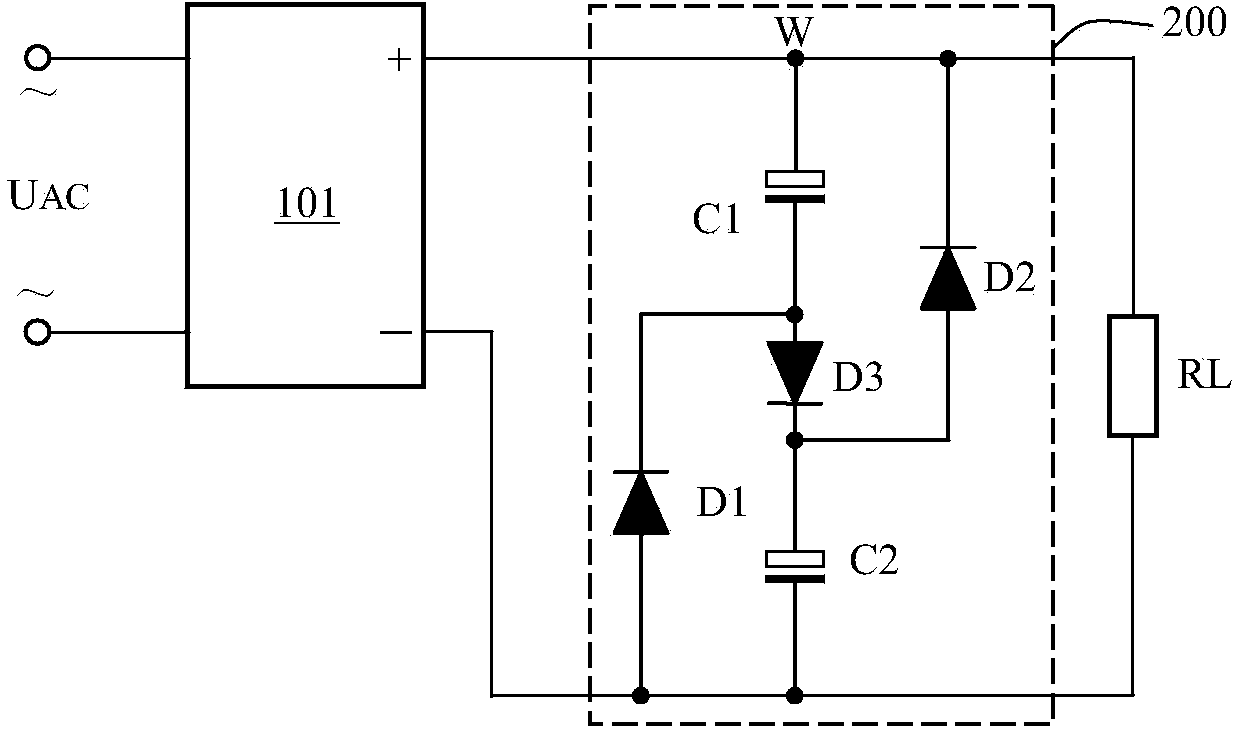
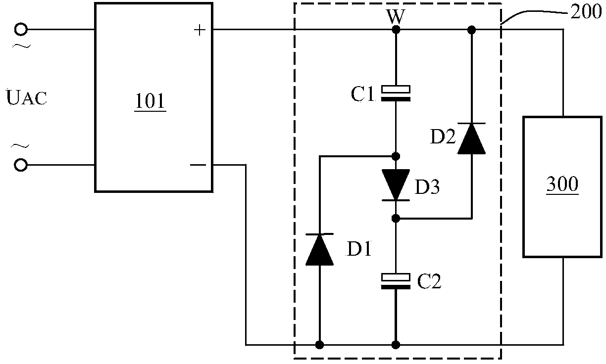
[0041] Figure 5 The schematic diagram of the valley filling circuit of the first embodiment is shown, a valley filling circuit 201 is used to be connected between the rectifier circuit 101 and the flyback circuit 300, including

[0042] The first capacitor C1 and the first diode D1, the anode of the first capacitor C1 is connected to the positive output terminal of the preceding rectifier circuit, the cathode of the first capacitor C1 is connected to the cathode of the first diode D1, and the first diode D1 The anode of the anode is connected to the negative output terminal of the pre-stage rectifier circuit;

[0043] The second capacitor C2 and the second diode D2, the cathode of the second capacitor C2 is connected to the anode of the first diode D1, the anode of the second capacitor C2 is connected to the anode of the second diode D2, and the second diode D2 The cathode of the first capacitor C1 is connected to the positive pole;

[0044] a third diode D3, the anode of t...

no. 2 example

[0076] Image 6 Shows the circuit schematic diagram of the second embodiment, a valley filling circuit 201', which differs from the first embodiment in that it further includes a resistor R1, which is connected in series with a diode D3 to form a two-terminal device, the two-terminal The device replaces the diode D3 in the first embodiment, and keeps the current direction of the diode D3 unchanged, that is, the function of the charging diode D3 to charge the capacitors C1 and C2 only when the AC current is close to the peak value remains unchanged. The resistor R1 is connected in series with the diode D3, and the capacitor C3 is connected in parallel to both ends of the two-terminal device formed by connecting the first resistor R1 and the third diode D3 in series. The resistor R1 connected in series with the diode D3 is used to improve when the input AC voltage is close to the peak value. The pulse width of the charging current further improves the power factor of the present...


PUM

PropertyMeasurementUnit
Capacitanceaaaaaaaaaa

Abstract

The invention discloses a valley filling circuit. A third capacitor C3 is connected to a charging diode D3 in an existing valley filling circuit in parallel, and therefore the withstand voltage of the third capacitor C3 is half the peak value of the input pulsating direct current, and the high-frequency ripple current of a back-stage switching power supply 300 can be fully and effectively absorbed. Due to the fact that the third capacitor does not directly discharge to a load 300, the power factor of the valley filling circuit is large, no high-voltage capacitor which is high in cost and large in size is needed, the capacity value of the third capacity is easy to obtain, and no average striking is needed.

Description

technical field [0001] The invention relates to the field of rectification and filtering, in particular to a valley filling circuit used between a rectification circuit and a flyback switching power supply circuit. Background technique [0002] Both industrial and civil use often need to change the AC voltage of various power grids into DC, or even isolated DC. With the further requirements of the national standard on the power factor of electrical appliances, at present, there are switching power supplies with a power consumption of more than 75W. The power factor requirement means that the operating current waveform of the circuit is basically the same as the voltage waveform. [0003] At present, there is a power factor correction circuit to solve this problem. The power factor correction circuit is referred to as a PFC circuit for short, which is the abbreviation of Power Factor Correction. [0004] Note: The 75W data comes from the Chinese national standard GB17625.1-1...

Claims


Application Information

Patent Timeline
IPC IPC(8): H02M1/42H02M1/14
CPCY02B70/10
Inventor 王保均
Owner MORNSUN GUANGZHOU SCI & TECH
Why Eureka
Try Eureka