Simple demagnetization circuit

A circuit and demagnetization technology, applied in the field of electronics, can solve the problems affecting the on-off and disconnection of the circuit, and achieve the effect of fast demagnetization, high reliability and good demagnetization effect.

Inactive Publication Date: 2014-10-01
SUZHOU GUJI ELECTRONICS TECH
View PDF5 Cites 2 Cited by
  • Summary
  • Abstract
  • Description
  • Claims
  • Application Information

AI Technical Summary

Problems solved by technology

[0003] Electromagnetic clutches, contactors, etc. will not be disengaged in time due to residual magnetism after being used for a long time, which affects the on-off of the circuit

Method used


Image

  • Simple demagnetization circuit

Examples


Embodiment Construction

[0015] The present invention will be further described below in conjunction with the accompanying drawings. The following examples are only used to illustrate the technical solution of the present invention more clearly, but not to limit the protection scope of the present invention.

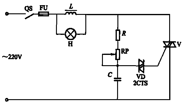
[0016] The simple demagnetization circuit of the present invention is used for demagnetizing magnetic devices such as electromagnetic clutches and contactors. Such as figure 1 As shown, the fuse FU, degaussing coil L, resistor R, potentiometer RP and capacitor C are connected in series in the 220V AC circuit. The on-off of the circuit is controlled by the isolation switch QS. Circuit protection is carried out by fuse FU.

[0017] An indicator light H is connected in parallel with both ends of the degaussing coil L, and the brightness of the indicator light H indicates the change of the voltage on the degaussing coil L.

[0018] After the resistance R, the potentiometer RP and the capacitor C...


PUM


Abstract

The invention discloses a simple demagnetization circuit. A demagnetizing coil, a resistor, a potentiometer and a capacitor are orderly connected in series to a 220V alternating current circuit; the two ends of the resistor, the potentiometer and the capacitor all connected in series previously are connected in parallel with a bidirectional thyristor; one end, connected with the bidirectional thyristor, of the capacitor is connected to one end of an alternating-current power source; a bidirectional trigger diode is arranged between one end, connected with the potentiometer, of the capacitor and the control electrode of the bidirectional thyristor, and the triggering of the bidirectional thyristor is controlled by the bidirectional trigger diode. The simple demagnetization circuit can be composed of conventional components, and is high in demagnetization speed, good in demagnetization effect, high in reliability and good in stability.

Description

[0001] technical field [0002] The invention relates to a simple demagnetization circuit, which belongs to the field of electronic technology. Background technique [0003] Electromagnetic clutches, contactors, etc. will not be disengaged in time due to residual magnetism after being used for a long time, which affects the on-off of the circuit. Therefore, it is necessary to regularly demagnetize this kind of device that is prone to residual magnetization to eliminate the magnetization phenomenon and ensure its reliability. Contents of the invention [0004] The technical problem to be solved by the invention is to overcome the defects of the prior art and provide a simple demagnetization circuit with low cost, fast demagnetization speed and good effect. [0005] In order to solve the above technical problems, the present invention provides a simple degaussing circuit, which is characterized in that a degaussing coil, a resistor, a potentiometer and a capacitor are conne...

Claims


Application Information

Patent Timeline
Patent Type & Authority Applications(China)
IPC IPC(8): H01F13/00
Inventor 罗宇新
Owner SUZHOU GUJI ELECTRONICS TECH
Why Eureka
Try Eureka