
Ultrasonic particle size analyzer

A particle size analysis and ultrasonic technology, applied in particle size analysis, particle and sedimentation analysis, analysis of materials, etc., can solve the problems of ultrasonic hardware not taking advantage of ultrasonic non-destructive detection, impossible to obtain particle size distribution, lack and other problems

Inactive Publication Date: 2014-10-01
PHARMAVISION QINGDAO INTELLIGENT TECH LTD
View PDF2 Cites 14 Cited by
  • Summary
  • Abstract
  • Description
  • Claims
  • Application Information

AI Technical Summary

Problems solved by technology

[0010] 1. Existing ultrasonic hardware usually does not take advantage of ultrasonic non-destructive detection and usually requires sampling or adding a long process to measure
[0011] 2. There is a lack of a model to correctly describe the interaction of ultrasound in different materials, sound frequencies and dispersed phase concentrations. Existing models are either only applicable to long-wave band situations, or in the case of low concentrations
[0012] 3. The inversion of the attenuation spectrum involves the solution of optimization problems with multiple highly nonlinear local solutions, and such problems often have no ordinary solutions
[0013] 4. The problem of "ambiguity" in the use of ultrasonic data to obtain particle size distributions, because several different particle size distributions will obtain the same ultrasonic attenuation spectrum, which has been widely reported, which makes In some applications it is almost impossible to obtain a true particle size distribution
But its disadvantages are obvious
The ultrasonic transmitter receiver and the ultrasonic detection device are integrated, which makes the instrument too large so that it can only be measured offline or requires an external pipeline for online measurement

Method used


Image

  • Ultrasonic particle size analyzer
  • Ultrasonic particle size analyzer
  • Ultrasonic particle size analyzer

Examples


Embodiment Construction

[0032] The present invention will be further described below in conjunction with specific examples.

[0033] The ultrasonic particle size analyzer described in this embodiment includes a hardware part and a software part, wherein:

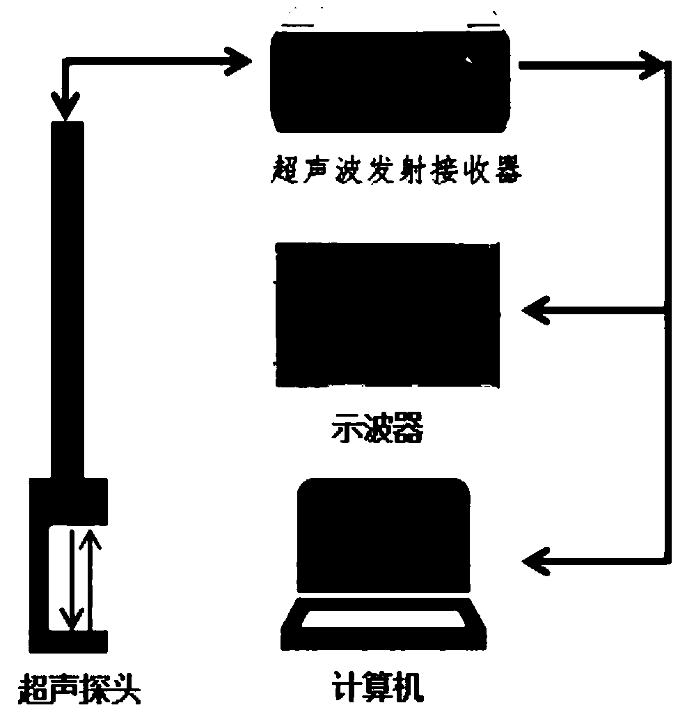
[0034] Such as figure 1 As shown, the hardware part includes an ultrasonic transmitter receiver and an ultrasonic detection device that are independent of each other, as well as an oscilloscope for real-time monitoring of the transmitted and received ultrasonic signals and a computer for data processing. The ultrasonic detection device adopts reflection mode or In transmission mode, it can be immersed in the sample for measurement or directly added to the existing pipeline for measurement.

[0035] When working, the ultrasonic transmitter receiver first sends out a high-frequency (1MHz-100MHz) ultrasonic signal, which propagates in the suspension through the ultrasonic detection device, changes its intensity after encountering particles, and then ...


PUM


Abstract

The invention discloses an ultrasonic particle size analyzer, which comprises a hardware part and a software part, wherein the hardware part comprises an ultrasonic wave transmitting and receiving device and ultrasonic detection devices which are independent mutually, as well as an oscilloscope and a computer; the software part comprises a plurality of ultrasonic models, five global optimization algorithms and an expert consultation mode. An ultrasonic pulse signal is generated by the ultrasonic transmitting and receiving device, the ultrasonic waves are transmitted to suspension liquid through different ultrasonic detection devices, the amplitudes of the ultrasonic waves are attenuated after the ultrasonic waves are interacted with particles in the suspension liquid, and at different frequencies, the attenuation of the amplitudes is different according to the sizes and volume fractions of particles; particle size distribution and volume fractions of required particles can be obtained after the collected attenuation signal is processed through the computer. The ultrasonic particle size analyzer provided by the invention can perform nondestructive measurement, is rapid, reliable, and particularly suitable for high-concentration non-transparent samples, and samples are not required to be diluted.

Description

technical field [0001] The invention relates to the technical field of particle size measurement, in particular to an ultrasonic particle size analyzer. Background technique [0002] In many industrial sectors, the technical problems closely related to fine particles need to be solved: such as the color particles in paints, their particle size has a great influence on the coloring power, hiding power, film-forming ability and stability of paints, etc. The measurement of particle size is one of the most basic and important aspects. In addition to this, the measurement of the particle concentration is also important. [0003] The commonly used particle size measurement methods are: screening method, microscope method, holographic method, electric induction method, sedimentation method and light scattering method. Most of the above measurement methods require sampling for measurement, although the light scattering method can be used for online measurement and has the advantag...

Claims


Application Information

Patent Timeline
IPC IPC(8): G01N15/02G01N29/032
Inventor 王学重阿基诺拉佛罗拉
Owner PHARMAVISION QINGDAO INTELLIGENT TECH LTD
Learn More