
Air-conditioning energy consumption monitoring and diagnosing system and method

An air-conditioning system and energy consumption monitoring technology, applied in space heating and ventilation, heating and ventilation control systems, heating and ventilation safety systems, etc. Changeable and other issues

Inactive Publication Date: 2014-10-01
国网电力科学研究院武汉能效测评有限公司 +3
View PDF4 Cites 20 Cited by
  • Summary
  • Abstract
  • Description
  • Claims
  • Application Information

AI Technical Summary

Problems solved by technology

[0003] At present, the technical transformation of air-conditioning equipment, PLC (programmable logic controller) intelligent control, and variable air volume control are the main means of air-conditioning energy-saving transformation. The alarm and diagnosis of equipment failure are the main means of automatic diagnosis of air-conditioning systems, but no single method Ensure the efficient and energy-saving operation of the air conditioning system
The coordination of air-conditioning system equipment, complex operation technology, and variable operating environment parameters require comprehensive consideration of technical factors in each link of the system in order to achieve the desired effect. At present, there is no independent device to help the operation and management of the air-conditioning system. Measure and track the energy efficiency of the refrigeration system in real time, evaluate the problems of the air conditioning system, and optimize the design of the air conditioning system

Method used


Image

  • Air-conditioning energy consumption monitoring and diagnosing system and method
  • Air-conditioning energy consumption monitoring and diagnosing system and method
  • Air-conditioning energy consumption monitoring and diagnosing system and method

Examples


Embodiment Construction

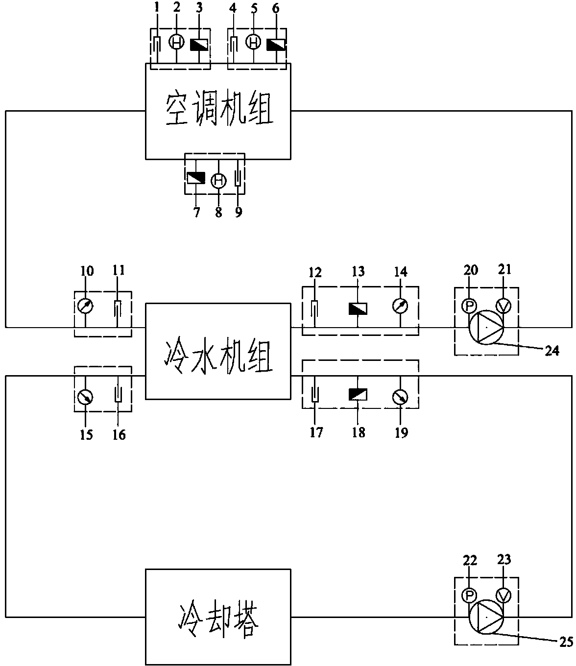
[0027] like figure 2 As shown, the two ends of the air conditioning unit are respectively connected with the chilled water inlet and outlet of the chiller, and the cooling water inlet and outlet of the chiller are respectively connected with the two ends of the cooling tower. The air conditioning unit is equipped with a temperature sensor 1 at the air supply end, a humidity sensor 2 at the air supply end, a flow sensor 3 at the air supply end, a temperature sensor 4 at the fresh air end, a humidity sensor 5 at the fresh air end, a flow sensor 6 at the fresh air end, and a flow sensor 7 at the return air end , the humidity sensor 8 at the return air end and the temperature sensor 9 at the return air end. The chilled water inlet of the chiller is provided with a chilled water inlet pressure sensor 10 and a chilled water inlet temperature sensor 11 . A chilled water pump 24 is connected between the chilled water outlet of the chiller and the air conditioner, and the chilled wat...


PUM


Abstract

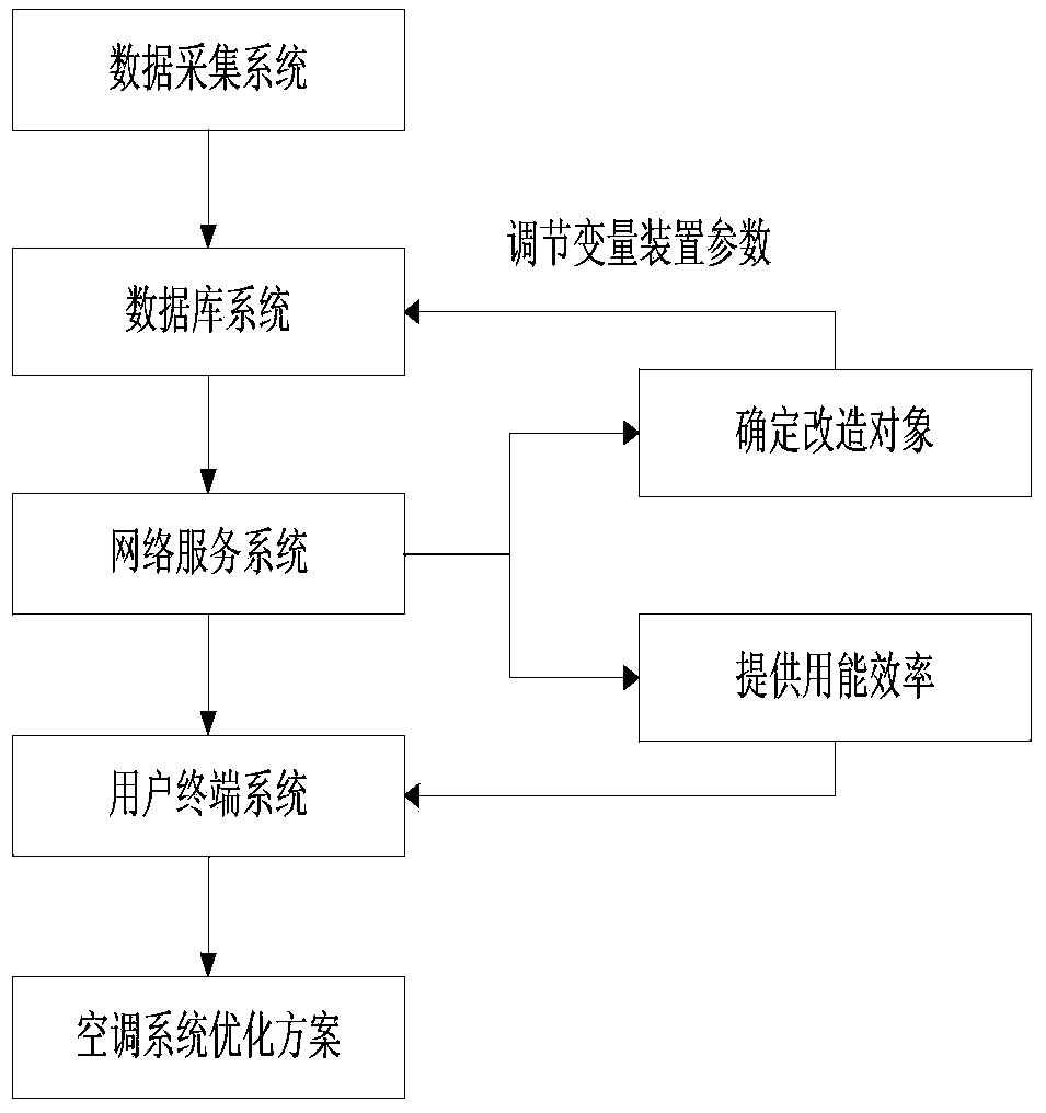
The invention relates to an air-conditioning energy consumption monitoring and diagnosing system and method. A data collection system, a database system, a network service system and a user terminal system provide air-conditioning system operation managers with real-time energy consumption monitoring data, diagnose energy conservation transformation objects and provide a system optimization design plan. The data collection system is mainly used for collecting original operation data of an air-conditioning system and a device of the air-conditioning system, the database system is mainly used for establishing an original database for operating the air-conditioning system and an adjustable variable base of the air-conditioning system, the network service system is mainly used for user management, energy consumption analyses and determination of transformation objects, and the user terminal system is used for providing the air-conditioning system with an energy conservation optimization transformation plan. The air-conditioning energy consumption monitoring and diagnosing system and method are capable of helping the air-conditioning system operation managers real-timely manage and trace energy efficiency of a refrigerating system, evaluate problems existing in the air-conditioning system, and optimize designs of the air-conditioning system.

Description

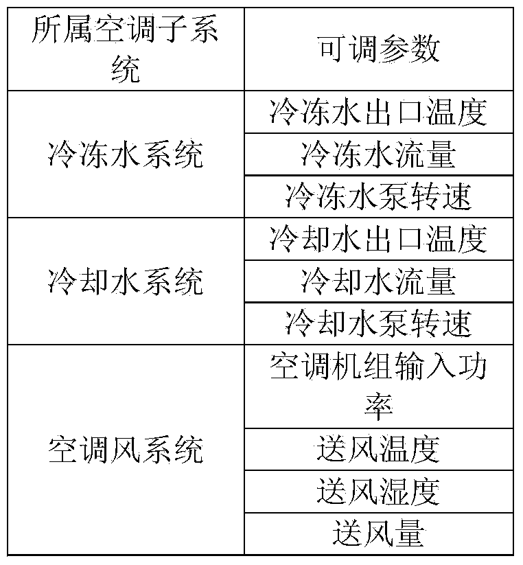
technical field [0001] The patent of the invention belongs to the field of energy consumption monitoring, and specifically relates to an air conditioner energy consumption monitoring and diagnosis system and method. Background technique [0002] In the context of global energy shortages, energy saving and consumption reduction are becoming increasingly urgent. The air-conditioning system has a large power and high energy consumption, which accounts for a large proportion of building energy consumption. Therefore, it is of practical significance to do a good job in energy-saving work of the air-conditioning system. [0003] At present, the technical transformation of air-conditioning equipment, PLC (programmable logic controller) intelligent control, and variable air volume control are the main means of air-conditioning energy-saving transformation. The alarm and diagnosis of equipment failure are the main means of automatic diagnosis of air-conditioning systems, but no singl...

Claims


Application Information

Patent Timeline
Patent Type & Authority Applications(China)
IPC IPC(8): F24F11/00
Inventor 邱泽晶肖楚鹏彭旭东王振宇向洁李文庆黄静
Owner 国网电力科学研究院武汉能效测评有限公司
Learn More