
High-rise escape device

An escape device and high-rise technology, applied in life-saving equipment, building rescue and other directions, can solve the problems of high risk, slow conveying speed, affecting the safety of escape personnel, etc., and achieve the effect of high safety and large conveying capacity.

Active Publication Date: 2014-10-01
SUZHOU INST OF TRADE & COMMERCE
View PDF7 Cites 2 Cited by
  • Summary
  • Abstract
  • Description
  • Claims
  • Application Information

AI Technical Summary

Problems solved by technology

[0003] In order to achieve self-rescue, it is more common to prepare escape tools such as ropes at home. If you use ropes to escape, you need to have relevant knowledge of rope escapes, otherwise you will accelerate the slide while using ropes, so secondary accidents will occur. , and there is the escape device at home or on the floor, see 201010244470.4 high-rise escape device and 201110125459.0 high-rise escape safety belt, these two escape devices include: safety belt / load-bearing rope, riding device, descent controller, escape personnel sit In the riding device, the descending speed of the safety belt / load-bearing rope is controlled by the controller to achieve the purpose of escape. This type of escape device can only transport one or two people at a time, and the conveying speed is slow, and a riding device must be equipped with A fixed bracket used to fix the safety belt / load-bearing rope, and the ride is placed in the air, and the person will swing when boarding the ride, which is very dangerous. During the descent, the ride will be affected by the wind and people shaking Affected, left and right swings occur, affecting the safety of escape personnel. In addition, when a fire occurs below the escape device, the escape device cannot be used
[0004] As mentioned above, the existing escape devices use their own weight to transport people from a high place to a low place. If a fire occurs below the escape device, the escape device cannot be used, and there are problems such as slow escape speed and low safety factor.

Method used


Image

  • High-rise escape device
  • High-rise escape device
  • High-rise escape device

Examples


Embodiment Construction

[0036] Hereinafter, the present invention will be further described in detail with reference to the drawings.

[0037] A high-rise escape device, including:

[0038] A base 1 with a guide rail 11;

[0039] A bracket 2, the bracket is arranged on the guide rail of the base and can move along the guide rail;

[0040] A transmission mechanism 3, including a motor 31 and a rotating shaft 32 arranged on a support, a rope 33 is arranged on the rotating shaft 32, and a plurality of protrusions 311 are arranged at the end of the output shaft of the motor;

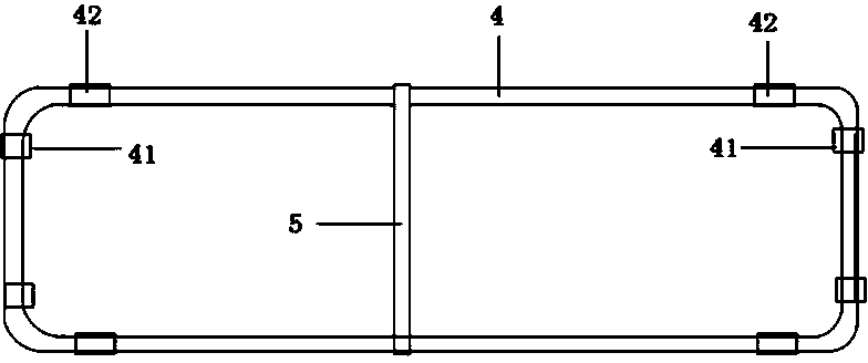
[0041] A conveying device 4, the conveying device is provided with a self-locking mechanism 41 and a pulley 42, the conveying device is fixed to the rope by the self-locking mechanism, and the conveying device is moved from one bracket to another by the movement of the rope;

[0042] A gear box 7, the gear box is arranged on the bracket, corresponding to the electric motor, the gear box is provided with a clutch 71, a transmission shaft 74, a...


PUM


Abstract

A high-rise escape device comprises a base, a transmission mechanism, a support, a gear case and a conveying device. The base is provided with a guide rail. The support is arranged on the guide rail of the base and can move along the guide rail. The high-rise escape device further comprises a motor and a rotating shaft which are arranged on the support. A rope is arranged on the rotating shaft. A self-locking mechanism and a pulley are arranged on the conveying device. The conveying device is fixed to the rope through the self-locking mechanism. The conveying device is moved from one support to another through movement of the rope. According to the high-rise escape device, self locking and unlocking are achieved through the weight of the conveying device, the locking speed is high, the conveying efficiency is high, and bidirectional delivery between a low position and a high position can be achieved.

Description

Technical field [0001] The invention relates to life-saving equipment, in particular to a high-rise escape device. Background technique [0002] With the development of society, the population is gradually shifting to large and medium-sized cities. Due to limited land resources, in order to solve the work and housing problems of a large number of migrants, urban buildings have developed to high-rise buildings. High-rise buildings can solve the housing problem and the safety The problem is also in front of people, especially when a fire occurs, people escape from safe passages or wait for rescue. From safe passages and waiting for rescue, some unpredictable situations often occur and miss the best escape opportunity. . [0003] In order to achieve self-rescue, it is more common to prepare escape tools such as ropes at home. Using ropes to escape requires relevant rope escape knowledge. Otherwise, the ropes will accelerate and slide during sliding, so secondary accidents will occur....

Claims


Application Information

Patent Timeline
IPC IPC(8): A62B1/06A62B1/18
Inventor 陈福明
Owner SUZHOU INST OF TRADE & COMMERCE
Learn More