Sprinkler

A sprinkler head and sprinkler technology, which is applied to spray devices, spray devices, liquid spray devices, etc., can solve the problems of increased material cost, manufacturing cost, and less ability to reduce the working load of the operating lever, and achieves lightening the working load, increasing the The effect of workload

Active Publication Date: 2016-08-24
TAKAGI CO LTD
View PDF7 Cites 0 Cited by
  • Summary
  • Abstract
  • Description
  • Claims
  • Application Information

AI Technical Summary

Problems solved by technology

[0020] However, in the sprinkler head of Patent Document 1, in order to reduce the operating load on the operating lever, the annular packing made of a special material, the E-ring for preventing the annular packing from coming off, and assembly processing are required. , therefore, material cost, manufacturing cost increase
[0021] In addition, when the water pressure of the water pipe is high, when the water is stopped, the valve core part of the second valve, which becomes the opening and closing valve core, is strongly trapped in the annular packing due to the hydraulic pressure, and the second valve is closed. When opening, a large force is required, and there is a problem that it is difficult to reduce the operating load of the operating lever.

Method used


Image

  • Sprinkler
  • Sprinkler
  • Sprinkler

Examples


no. 2 approach >

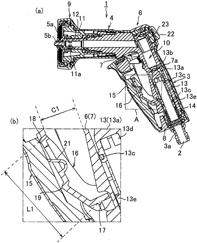
[0146] In the first embodiment, the first point of force portion 18 and the second point of force portion 19 are provided on the relay lever 16, but it is also possible to set more than three point of force portions with different distances from the fulcrum portion 17. When the lever 15 is gripped from the water-stop position to the fully open position, it abuts against the operating lever 15 sequentially from the point of force farthest from the fulcrum 17 .

[0147] In addition, the arm extending upward of the relay lever 16 may also be formed into a curved shape convex forward, and when the operating lever 15 is gripped from the water stop position to the fully open position, the point of force abutting the operating lever 15 will be reduced. The portion changes continuously from the anterior end to the proximal end of the arm.

[0148] In addition, in the first embodiment, only the section from the second force point portion 19 to the fulcrum portion 17 may be formed in a ...

no. 3 approach >

[0150] In the first embodiment, the first point of force 18 and the second point of force 19 are provided on the relay rod 16, but it is also possible to form only one point of force, instead of setting two or more points of force starting from the fulcrum portion 17. Different distances from the point of action.

[0151] In this case, at the water stop position, the action point formed at the nearest point of the fulcrum 17 abuts against the on-off valve core. The action point portions come into contact with the on-off valve body in order from the action point portion close to the fulcrum portion 17 .

[0152] According to this, similarly to the first embodiment, the workload of the operation lever 15 can be effectively reduced, and the on-off valve can be effectively opened and closed.

[0153]

[0154] In the first embodiment, the lower end of the operating rod 15 is used as a fixed end, and the upper end is used as a free end. However, the upper end of the operating rod...


PUM


Abstract

A sprinkler head (1), comprising a sprinkler body (6) with a water flow path (10) formed therein, capable of being mounted on the sprinkler body (6) in an approachable and detachable manner The rod (15), the on-off valve (13) for opening and closing the flow path (10), has a fulcrum (17) rotatably supported on the spray head body (6), and a contact with the operating rod (15). Power point parts (18, 19) and the relay rod (16) of the action point part (20) abutted with the on-off valve (13), the relay rod (16) and the operating rod (15) and the nozzle main body (6) The positional relationship of the valve rotates correspondingly to open and close the on-off valve (13). Among them, two or more power point parts (18, 19) with different distances from the fulcrum part (17) are set on the relay rod (16). , at the water-stop position of the on-off valve (13), the point of force (18) formed farthest from the fulcrum (17) is abutted against the operating rod (15), and the opening ratio of the on-off valve (13) is At a position where the predetermined degree is large, another point of force (19) is brought into contact with the operating rod (15). According to the above configuration, in the sprinkler head, even in the state of high water pressure at the water stop position, the workload on the control lever can be reduced.

Description

technical field [0001] The present invention relates to a sprinkler head which is mainly used in gardening, cleaning, agriculture, etc. at home, and is connected to the front end of water supply equipment such as a water pipe through a hose to diffuse water, especially relates to a sprinkler head which is held in the user's hand and operated. Background technique [0002] In households, a sprinkler head that is attached to the tip of a hose and optionally switches between spraying and stopping water is widely used in gardening, agriculture, cleaning, and the like. Such a sprinkler head receives water supply from a water supply facility such as a water pipe through a hose, and sprays water from a sprinkler port formed at the front end. [0003] Previous sprinkler nozzles 25 such as Figure 8 As shown, a flow path 10 for water connecting the inlet port at the base end to the spray port 5a at the front end is formed in the shower head main body 6, and an opening and closing val...

Claims


Application Information

Patent Timeline
Patent Type & Authority Patents(China)
IPC IPC(8): B05B1/30B05B1/18
CPCB05B1/18B05B1/3013B05B12/002B05B1/1627B05B9/01
Inventor 砂场孝行汤川大树
Owner TAKAGI CO LTD
Why Eureka
Try Eureka