
Method for forming fin field effect transistor

A fin field effect and transistor technology, which is applied in the fields of semiconductor devices, semiconductor/solid-state device manufacturing, electrical components, etc., can solve the problems that affect the performance of fin field effect transistors and cannot completely remove the sidewall material layer, etc.

Active Publication Date: 2017-05-17
SEMICON MFG INT (SHANGHAI) CORP
View PDF3 Cites 0 Cited by
  • Summary
  • Abstract
  • Description
  • Claims
  • Application Information

AI Technical Summary

Problems solved by technology

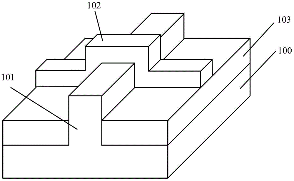
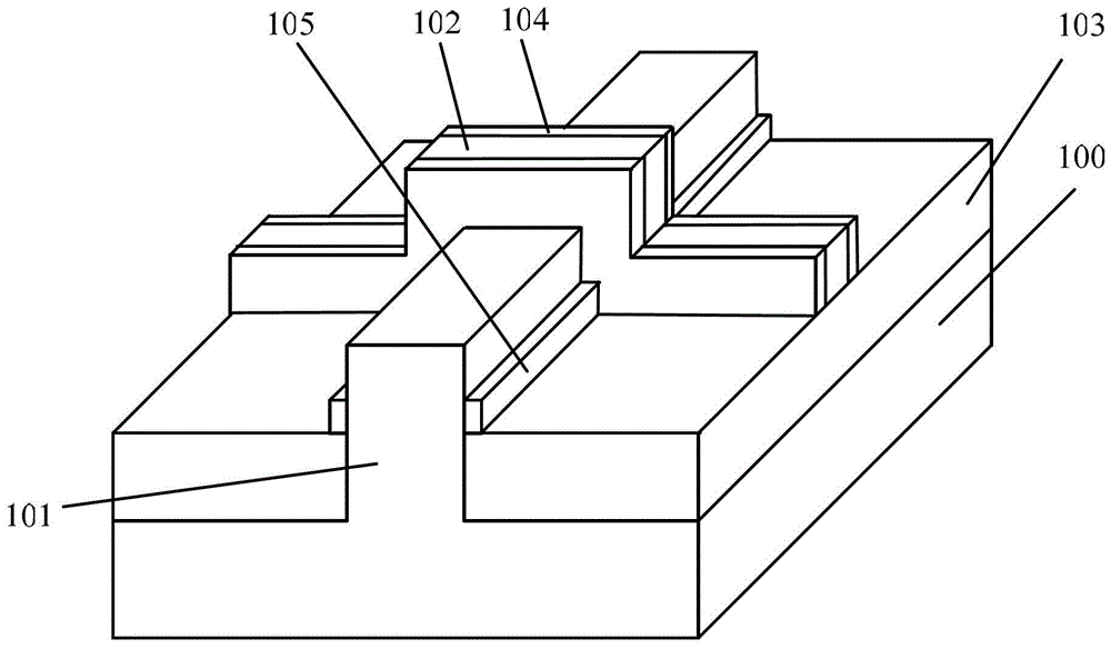
However, since the fin portion 101 protrudes from the surface of the semiconductor substrate 100, a sidewall material layer will also be formed on the side wall surface of the fin portion 101. Layers of side wall material on both sides of section 101
Residual sidewall material 105 will be formed at the contact portion between the bottom of the fin portion 101 and the isolation structure 103 , affecting the performance of the subsequently formed FinFET.

Method used


Image

  • Method for forming fin field effect transistor
  • Method for forming fin field effect transistor
  • Method for forming fin field effect transistor

Examples


Embodiment Construction

[0035] It can be seen from the background art that, in the prior art, during the formation of the sidewall of the fin field effect transistor, there will be residual sidewall material at the bottom of the fin.

[0036] The inventors of the present invention have studied the formation process of the sidewall in the prior art fin field effect transistor, please continue to refer to figure 1 and figure 2 It is found that in the prior art, after forming the sidewall material layer covering the fin portion 101 and the gate 102 , the sidewall material layer is directly etched back to form the sidewall 104 . However, since the fins 101 protrude from the surface of the semiconductor substrate 100, and the etching is generally anisotropic dry etching, after the etch-back process, the sides located on both sides of the fins 100 The wall material layer cannot be completely removed, which affects the performance of the subsequently formed FinFET. Further, the inventors of the present i...


PUM


Abstract

A method for forming a fin field-effect transistor comprises the steps of: providing a semiconductor substrate, wherein the surface of the semiconductor substrate is provided with a projected fin part and a gate electrode on the fin part, wherein the gate electrode covers top and side wall of partial fin part; forming a side wall material layer which covers the fin part and the gate electrode; performing ion injection on the side wall material part which covers the fin part, for forming a modified side wall material layer, wherein the etching speed of the modified side wall material layer is larger than the etching speed of the side wall material layer; and eliminating the modified side wall material layer which covers the fin part and a side wall material layer on the top surface of the gate electrode, and forming side walls at two sides of the gate electrode. According to the method for forming the fin field-effect transistor, in forming the side walls, side wall material does not residue at two sides of the bottom of the fin part, thereby facilitating transistor performance improvement.

Description

technical field [0001] The invention relates to the technical field of semiconductors, in particular to a method for forming a fin field effect transistor. Background technique [0002] MOS transistors generate switching signals by regulating the current through the channel region by applying a voltage to the gate. With the development of semiconductor technology, the control ability of the traditional planar MOS transistor on the channel current becomes weaker, resulting in serious leakage current. Fin Field Effect Transistor (Fin FET) is an emerging multi-gate device, which generally includes semiconductor fins protruding from the surface of the semiconductor substrate, and a gate structure covering part of the top and side walls of the fins. The source region and the drain region in the fins on both sides of the gate structure. [0003] During the fabrication of the FinFET, sidewalls on both sides of the gate are usually formed. [0004] figure 1 and figure 2 It is ...

Claims


Application Information

Patent Timeline
Patent Type & Authority Patents(China)
IPC IPC(8): H01L21/28H01L21/336
CPCH01L21/28008H01L29/401H01L29/66803
Inventor 三重野文健
Owner SEMICON MFG INT (SHANGHAI) CORP
Learn More