
LiDAR 3D Imaging System Based on Virtual Instrument

A technology of three-dimensional imaging and laser radar, which is applied in the direction of instruments, radio wave measurement systems, electromagnetic wave re-radiation, etc., can solve problems such as no occurrence, achieve strong expansion performance, shorten development cycle, and have rich functions

Active Publication Date: 2017-06-16
NANJING UNIV
View PDF3 Cites 3 Cited by
  • Summary
  • Abstract
  • Description
  • Claims
  • Application Information

AI Technical Summary

Problems solved by technology

[0017] Among the existing technical achievements, there is no Lidar 3D imaging system that can not only control the lidar simulation experiment scene in an integrated manner, but also provide a hardware module interface for the application platform to realize the extended application of the lidar actual measurement experiment.

Method used


Image

  • LiDAR 3D Imaging System Based on Virtual Instrument
  • LiDAR 3D Imaging System Based on Virtual Instrument
  • LiDAR 3D Imaging System Based on Virtual Instrument

Examples


Embodiment Construction

[0044] The technical implementation of the present invention will be described in detail below in conjunction with the accompanying drawings.

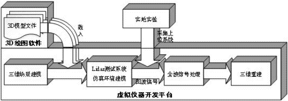
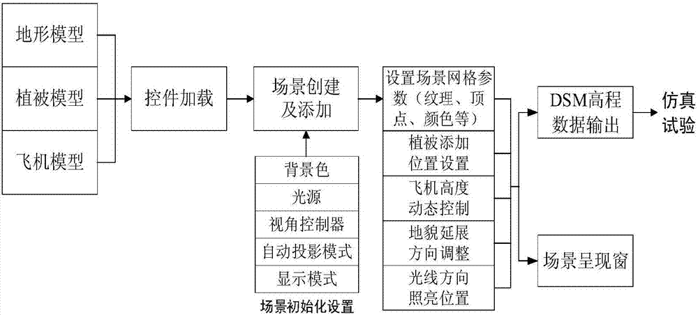
[0045] like figure 1 As shown, the present invention mainly includes four functional modules: three-dimensional scene modeling, Lidar test system simulation environment modeling, full-wave signal processing, and three-dimensional reconstruction. Among them, the 3D scene modeling module can load the 3D model components output by the 3D drawing software, and arrange and adjust them to produce the required experimental scene. The way to create 3D model components is rich and flexible. For example, terrain model elements can use the terrain and landform plug-in terrian plug-in in 3dsmax to generate actual digital terrain with specified latitude and longitude by connecting to GIS; vegetation models can use 3dsmax tree-building plug-ins to construct specified vegetation groups; aircraft models can be created in AutoCAD according to size req...


PUM


Abstract

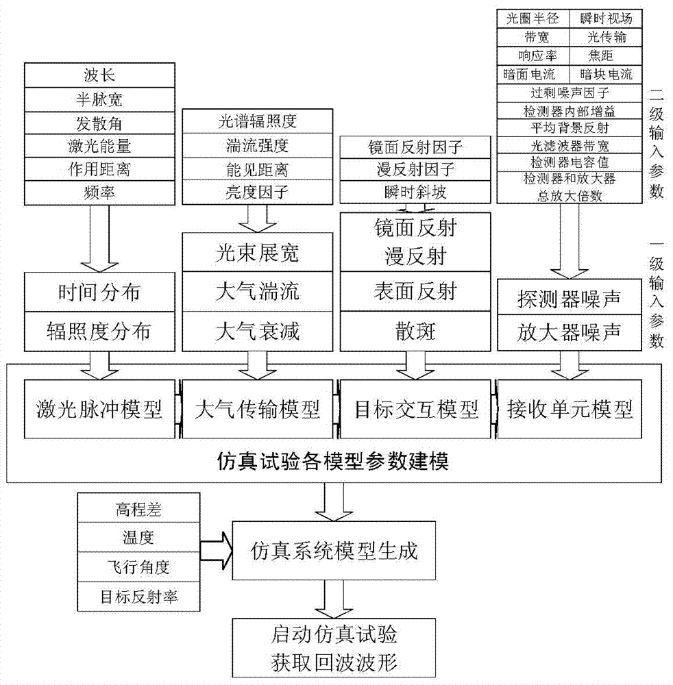
A lidar three-dimensional imaging system based on a virtual instrument comprises a three-dimensional scene modeling module, a lidar testing system simulation environment modeling module, a full-waveform signal processing module and a three-dimensional reconstruction module. The three-dimensional scene modeling module comprises a three-dimensional model loading element used for setting background colors, visual angle control, illumination, a projection mode, a display model and other basic scene projects. The lidar testing system simulation environment modeling module comprises four modeling sub-modules which are a laser pulse model, an atmospheric transmission model, an object interaction model and a receiving unit model. The laser pulse model is used for simulating a laser source according to the wavelength, pulse width, energy and other characteristics of a laser. The atmospheric transmission model is used for simulating a tested atmospheric environment, so that a noise model is generated for acting on the laser. The object interaction model is used for simulating effects of the laser and a detected object, and the effects comprise mirror reflection, diffuse reflection, surface reflection and speckles. The receiving unit model is used for simulating detector noise and amplifier noise which are generated after sensing.

Description

[0001] 1. Technical field [0002] The invention is a laser radar three-dimensional imaging system based on a virtual instrument, and belongs to the technical field of laser radar detection. [0003] 2. Background technology [0004] Lidar detection and ranging system (Lidar for short) is an active remote sensing technology. It breaks through the traditional passive remote sensing imaging mechanism. comparative advantage. [0005] The airborne imaging Lidar is corrected by the IMU position, and the DGPS acquires the projection center position of the device. The IMU / DGPS system refers to the use of the GPS receiver installed on the aircraft and the GPS receiver on one or more base stations on the ground to synchronize and continuously Observing GPS satellite signals from the earth, obtaining the position parameters of the aerial camera through GPS carrier phase measurement differential positioning technology, and directly measuring the attitude of the aerial camera by using a h...

Claims


Application Information

Patent Timeline
Patent Type & Authority Patents(China)
IPC IPC(8): G01S17/89G01S7/497
CPCG01S7/497G01S17/89
Inventor 王元庆徐帆曾真
Owner NANJING UNIV
Learn More