
Novel connecting structure capable of achieving replacement of steel coupling beams

A connection structure, a new type of technology, applied in the direction of building components, building structures, earthquake resistance, etc., can solve the requirements of replacing energy-dissipating beams after earthquakes, large shear force and bending moment at the connection, and bolt slippage at the connection, etc. Problems, to achieve the effect of excellent economy, high ability to transmit shear force, and ensure integrity

Inactive Publication Date: 2014-09-17
TSINGHUA UNIV
View PDF5 Cites 33 Cited by
  • Summary
  • Abstract
  • Description
  • Claims
  • Application Information

AI Technical Summary

Problems solved by technology

The welding connection is reliable in force transmission, but it is not detachable, and cannot meet the replacement requirements of the energy-dissipating beam section (or damper) after the earthquake
The bolted connection is detachable, but due to the large shear force and bending moment at the connection, a large number of high-strength bolts need to be laid out. However, in actual engineering, due to the limited connection surface, the arrangement of bolts is difficult or even impossible.
Previous experimental studies have also shown that even if friction-type high-strength bolts are used for connection, under the reciprocating action of a large earthquake, bolt slippage at the connection may also occur

Method used


Image

  • Novel connecting structure capable of achieving replacement of steel coupling beams
  • Novel connecting structure capable of achieving replacement of steel coupling beams
  • Novel connecting structure capable of achieving replacement of steel coupling beams

Examples


Embodiment Construction

[0023] The present invention will be described in further detail below in conjunction with the accompanying drawings and specific embodiments.

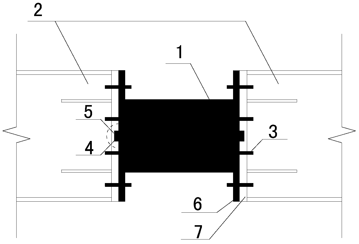
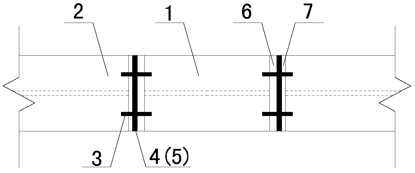
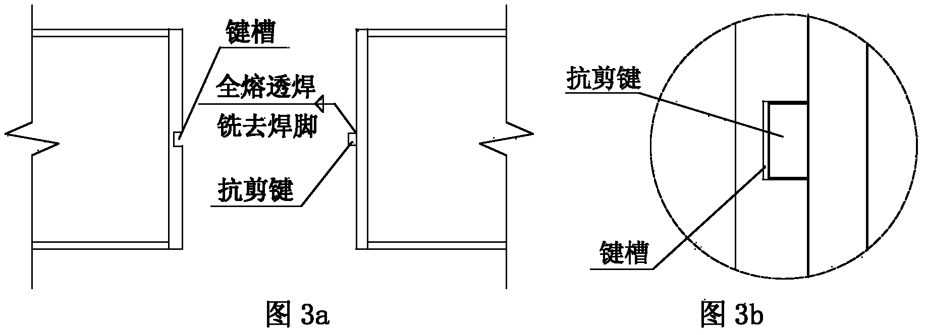
[0024] Such as figure 1 , figure 2 and image 3 As shown, the present invention is a new connection structure of replaceable steel connecting beams. An energy-dissipating beam section end plate 6 and a non-energy-dissipating beam section end plate 7 are respectively arranged at the ends of the connection between the energy-dissipating beam section 1 and the non-energy-dissipating beam section 2. A shear key 4 is provided on the end plate 6 of the energy-dissipating beam section at the end of the energy-dissipating beam section 1, and a shear key 4 is provided on the end plate 7 of the non-energy-dissipating beam section at the end of the non-energy-dissipating beam section 2 and the end plate 6 of the energy-dissipating beam section 4. A keyway 5 is provided at the corresponding position; a bolt hole for high-strength bolts 3 is pr...


PUM


Abstract

Provided is a novel connecting structure capable of achieving replacement of steel coupling beams. An energy dissipation beam section end board and a non-energy dissipation beam section end board are arranged at the connecting ends of an energy dissipation beam section and a non-energy dissipation beam section respectively, a shear key is arranged on the energy dissipation beam section end board, a key slot is formed in the position, corresponding to the shear key on the energy dissipation beam section end board, on the non-energy dissipation beam section end board, bolt holes connected with a high-strength bolt are further formed in the corresponding positions of the energy dissipation beam section end board and the non-energy dissipation beam section end board, the shear key bears the shearing force of the position where the energy dissipation beam section and the non-energy dissipation beam section are connected, and the high-strength bolt bears the bending moment of the position where the energy dissipation beam section and the non-energy dissipation beam section are connected. The novel connecting structure is reliable in force transmission under the action of a strong earthquake and is convenient to disassemble after the strong earthquake happens, fast replacement of the energy dissipation beam section can be ensured, the coupling beams can be repaired fast, and consequently the capacity of post-earthquake function fast recovery of high-rise building structures is improved.

Description

technical field [0001] The invention relates to the field of construction engineering and anti-seismic technology of structures, in particular to a novel connecting structure of replaceable steel connecting beams. Background technique [0002] High-rise and ultra-high-rise buildings are one of the main architectural forms of modern cities, and shear wall structure or frame-shear wall structure is a structural system widely used in high-rise buildings. Coupling beams are energy-dissipating components of shear wall structures or frame-shear wall structures. However, due to their small span-to-height ratios, reinforced concrete coupling beams are prone to shear failure, have poor deformation and energy dissipation capabilities, and are difficult to repair after earthquakes. In recent years, a replaceable steel connecting beam has been proposed, which consists of a replaceable energy-dissipating beam section (or damper) in the middle of the span and non-energy-dissipating beam s...

Claims


Application Information

Patent Timeline
IPC IPC(8): E04B1/58E04B1/98
Inventor 纪晓东王彦栋马琦峰钱稼茹
Owner TSINGHUA UNIV
Learn More