
Nozzle systems for edgebanding plants impinging hot air on adhesive-free, heat-activatable or provided edgebands or workpieces with hot-melt adhesive and edgebanding systems with nozzle systems

An adhesive-free, edge-banding technology, used in other plywood/plywood appliances, manufacturing tools, wood processing appliances, etc., can solve the problems of technical difficulties in the process, damage to the visual image, unsatisfactory operation speed, etc. High exothermic effect

Active Publication Date: 2016-05-25
霍尔根·克卢格
View PDF7 Cites 0 Cited by
  • Summary
  • Abstract
  • Description
  • Claims
  • Application Information

AI Technical Summary

Problems solved by technology

It has been found that the use of adhesives when applying edge strips to narrow sides of workpieces has several disadvantages
In addition to process-technical difficulties, there is often the problem that the adhesive layer remains visible to the observer after the edgeband has been applied to the workpiece and thus impairs the visual image
However, the operating speeds achievable so far are still unsatisfactory

Method used


Image

  • Nozzle systems for edgebanding plants impinging hot air on adhesive-free, heat-activatable or provided edgebands or workpieces with hot-melt adhesive and edgebanding systems with nozzle systems
  • Nozzle systems for edgebanding plants impinging hot air on adhesive-free, heat-activatable or provided edgebands or workpieces with hot-melt adhesive and edgebanding systems with nozzle systems
  • Nozzle systems for edgebanding plants impinging hot air on adhesive-free, heat-activatable or provided edgebands or workpieces with hot-melt adhesive and edgebanding systems with nozzle systems

Examples


Embodiment Construction

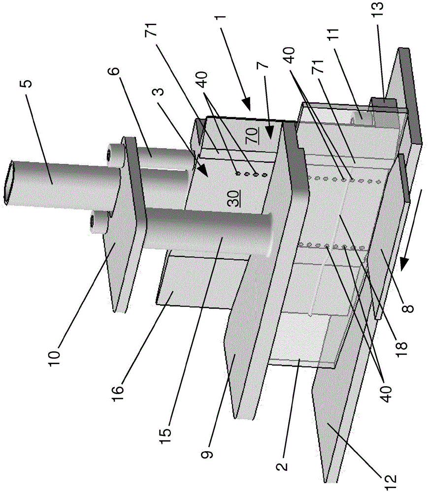
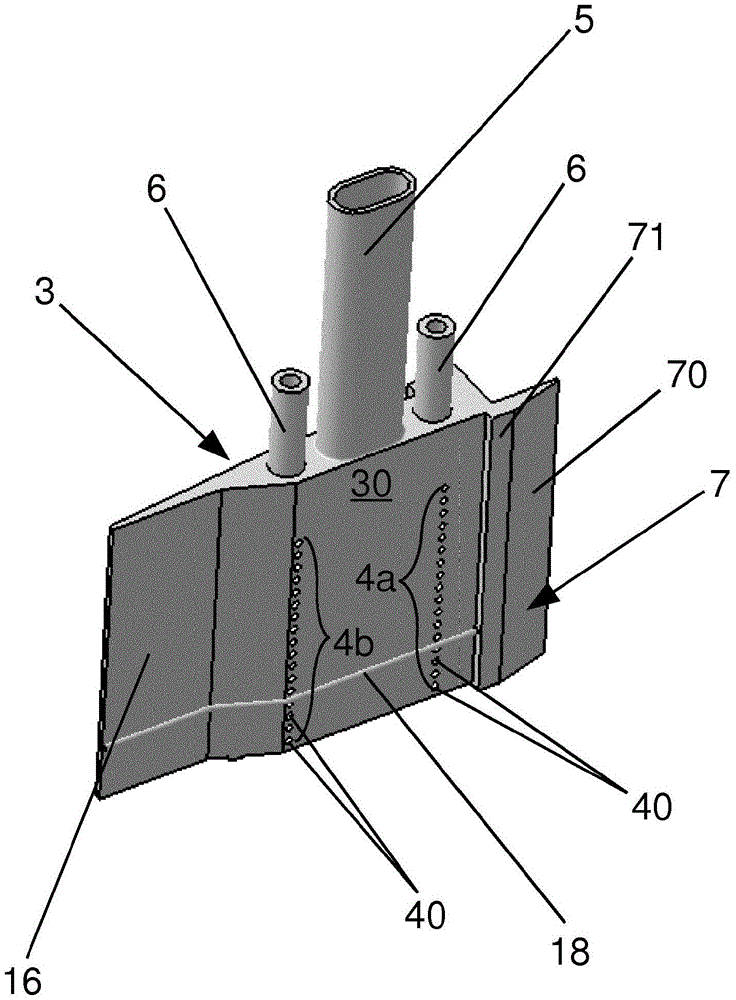
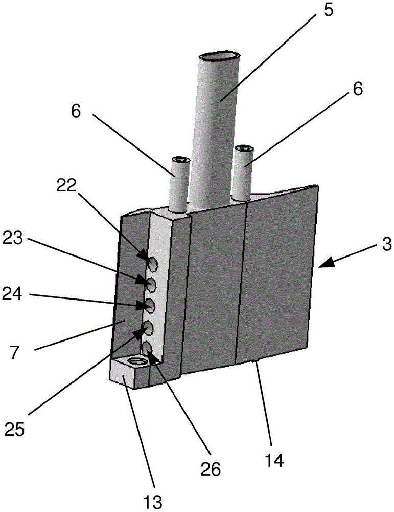
[0031] The following should refer to figure 1 The basic design and structure of the nozzle system 1 according to a preferred embodiment of the present invention is further explained. The nozzle system is used for the adhesive-free, heat-activatable edge banding 2 to impact hot air edge banding. equipment. The nozzle system 1 includes a nozzle body 3, which in this embodiment is made of heat-resistant steel in one piece. The nozzle body 3 is shaped so that it is transverse to the figure 1 The feeding direction of the edge band 2 indicated by the arrow in is configured to be relatively narrow, because the space available for the positioning of the nozzle system 1 in the edge band application equipment is usually relatively narrow. The nozzle system 1 is arranged in the edge band processing equipment in such a way that the nozzle system is positioned directly in front of the first edge band pressing roller along the feed direction of the edge band 2, and the edge band 2 uses the f...


PUM

PropertyMeasurementUnit
thicknessaaaaaaaaaa

Abstract

The invention relates to a nozzle system (1) for an edgeband application device (1) for impinging hot air on edgebands (2) or workpieces that are adhesive-free, heat-activatable or provided with hot-melt adhesive, the The nozzle system comprises a nozzle body (3), which has: at least one air inlet channel (20, 21), which can be connected to the hot air generator, so that the nozzle can be supplied during the operation of the edge strip application equipment. The body (3) conveys high-pressure hot air; at least two groups (4a, 4b, 4c) of air outlets (40), wherein the air outlets (40) are vertically spaced apart from each other and are constructed on the nozzle body (3) On the air ejection surface (30) facing the edge banding (2) and in flow connection with the at least one air inlet channel (20, 21), so that the at least two groups (4a, 4b, 4c) of air ejection ports ( 40) The feeding direction of the edge banding strip (2) is spaced apart from each other, and the hot air fed to the nozzle body (3) can flow out from the air outlet (40) and can impact the heatable air of the edge banding strip (2). Activated functional layer; the same number of closure devices (6, 6') as the number of groups (4a, 4b, 4c) of air discharge openings (40), which are constructed in such a way that the air discharge openings (40 ) can be selectively opened or closed in relation to the width of the conveyed edge strip (2).

Description

Technical field [0001] The invention relates to a nozzle system for an adhesive-free, heat-activatable or hot-melt adhesive-free edge-banding strip or an edge-banding strip coating equipment that impacts hot air on a workpiece. In addition, the present invention relates to an edge banding device with a nozzle system. Background technique [0002] As we all know, there are various different implementations of edge banding equipment (usually called edge gluing equipment) in the prior art. With these edge banding equipment, the edge banding can be applied to the workpiece. On the narrow side. The edge bands, which are also commonly referred to as Umleimer tapes, can for example have a heat-activatable adhesive on one side. The adhesive is activated by impacting hot air or hot air in the edge banding equipment, so that after the edge banding is pasted and pressed to the narrow side of the workpiece, the material of the edge band and the narrow side can be locked. (Stoffschluessig)...

Claims


Application Information

Patent Timeline
Patent Type & Authority Patents(China)
IPC IPC(8): B29C65/10
CPCB27D5/003B29C65/10B29C63/003B29C63/0065B29C65/16B29C65/4815B29C65/7841B29C66/028B29C66/112B29C66/114B29C66/472B29C66/723B29C66/7487B29C66/836B29C66/84121B29C66/919B29C66/939B29C66/9141B29C66/934B27D5/00B05B1/24
Inventor 霍尔根·克卢格
Owner 霍尔根·克卢格
Learn More