
Magnetorheological damper with float ring and double outlet rods

A magneto-rheological damper and floating ring technology, applied in vibration suppression adjustment, non-rotational vibration suppression, etc., can solve the problem of small adjustment range of damping force, and achieve the effect of wide adjustment range and large damping application range

Active Publication Date: 2014-09-10
STATE GRID CORP OF CHINA +1
View PDF6 Cites 3 Cited by
  • Summary
  • Abstract
  • Description
  • Claims
  • Application Information

AI Technical Summary

Problems solved by technology

[0002] Magneto-rheological damper is an intelligent damping device. The existing magneto-rheological damper mostly adopts the structure of piston and working cylinder. This type of magnetorheological damper changes the current entering the excitation coil in the piston to make the The change of the electromagnetic field intensity in the annular gap between the outer diameter and the inner diameter of the working cylinder (ie: the working gap) is used to adjust the viscosity of the magnetorheological fluid to adjust the damping force. Due to the work of this magnetorheological damper There is only one gap, so the range of damping force adjustment is small

Method used


Image

  • Magnetorheological damper with float ring and double outlet rods
  • Magnetorheological damper with float ring and double outlet rods
  • Magnetorheological damper with float ring and double outlet rods

Examples


Embodiment Construction

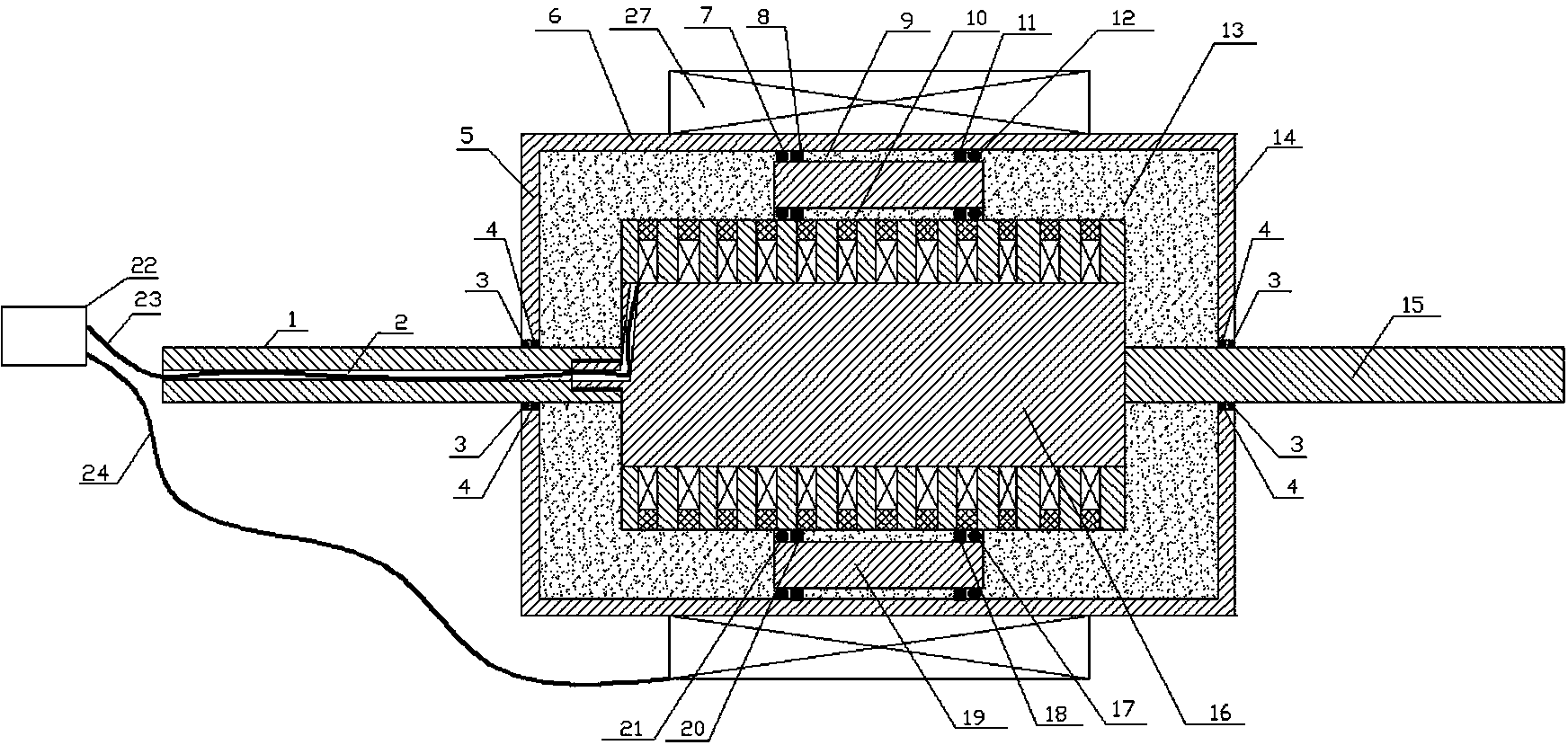
[0011] see figure 1 , figure 2 and image 3 , a magneto-rheological damper with floating rings and double rods, which includes a working cylinder 6, a floating ring 19, a piston 16, a piston rod 1, a piston rod 15 and an external electromagnet 27, wherein the working The cylinder 6 is cylindrical, and the two ends of the working cylinder 6 are fixed with an end cover 5 and an end cover 14. There is a hole in the center of the end cover 5 and the end cover 14, and a sealing device 4 and a sliding bearing 3 are installed in the hole; The floating ring 19 is made of magnetically permeable material; the piston 16 is made of a plurality of identical annular disks 26 fixed on the same stem 16, and is wound in the annular gap between the annular disks 26 of the piston 16. There is an exciting coil 25, and a protective layer 27 is installed outside the exciting coil 25. The protective layer 27 is flush with the outer peripheral wall of the piston 16; the piston 16 is installed in t...


PUM


Abstract

The invention discloses a magnetorheological damper with a float ring and double outlet rods. The magnetorheological damper comprises a working cylinder, the float ring, a piston, two piston rods and an external electromagnet. End covers are fixed to two ends of the cylindrical working cylinder; a plurality of identical annular discs are fixed onto the same core column to form the piston, and excitation coils are wound in annular gaps among the various annular discs of the piston; the piston is mounted in the working cylinder, and magnetorheological fluid flowing gaps are reserved between the outer peripheral wall of the piston and the inner peripheral wall of the float ring and between the outer peripheral wall of the float ring and the inner peripheral wall of the working cylinder; one ends of the two piston rods are respectively fixed to two ends of the piston, and the other ends of the two piston rods extend out of the two ends of the working cylinder via sealing devices and sliding bearings on the two end covers of the working cylinder; the gaps in the working cylinder, between the inner peripheral wall of the float ring and the outer peripheral wall of the piston and between the outer peripheral wall of the float ring and the inner peripheral wall of the working cylinder are filled with magnetorheological fluid; the external electromagnet is fixed onto the outer circumference of the working cylinder.

Description

technical field [0001] The invention relates to a magnetorheological damper, in particular to a magnetorheological damper with floating rings and double rods. Background technique [0002] Magneto-rheological damper is an intelligent damping device. The existing magneto-rheological damper mostly adopts the structure of piston and working cylinder. This type of magnetorheological damper changes the current entering the excitation coil in the piston to make the The change of the electromagnetic field intensity in the annular gap between the outer diameter and the inner diameter of the working cylinder (ie: the working gap) is used to adjust the viscosity of the magnetorheological fluid to adjust the damping force. Due to the work of this magnetorheological damper There is only one gap, so the range of adjustment of the damping force is small. Contents of the invention [0003] In order to overcome the shortcomings of the existing magnetorheological damper with only one work...

Claims


Application Information

Patent Timeline
IPC IPC(8): F16F9/53
Inventor 谭和平谢宁刘强谭晓婧
Owner STATE GRID CORP OF CHINA
Learn More