Scroll compressor

A technology of scroll compressors and moving scrolls, applied in the direction of rotary piston machinery, rotary piston pumps, mechanical equipment, etc.

Active Publication Date: 2014-09-10
TOYOTA IND CORP
View PDF7 Cites 2 Cited by
  • Summary
  • Abstract
  • Description
  • Claims
  • Application Information

AI Technical Summary

Problems solved by technology

The opposing wall is located in the housing and secured to the housing

Method used


Image

  • Scroll compressor
  • Scroll compressor
  • Scroll compressor

Examples


Embodiment Construction

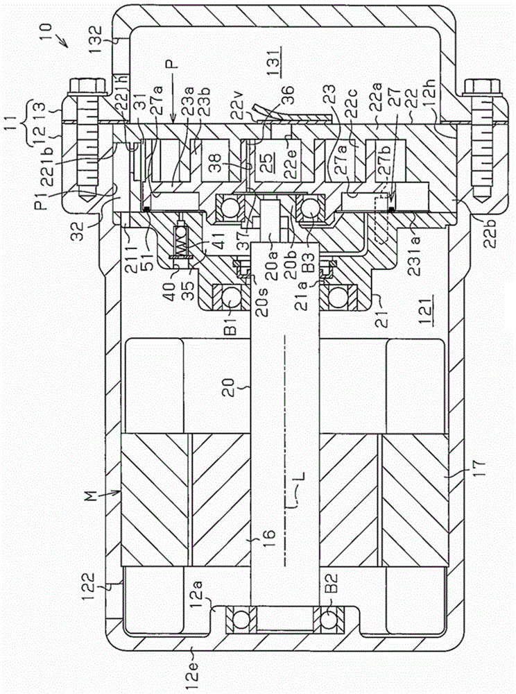
[0021] refer to Figure 1 to Figure 3 , one embodiment of a scroll compressor (hereinafter referred to as a compressor) will now be described. The compressor is installed in the vehicle and is used with the vehicle's air conditioner.

[0022] Such as figure 1 As shown in , a scroll compressor 10 includes a housing 11 made of metal (aluminum in this embodiment). The housing 11 includes a cylindrical motor housing member 12 and a cylindrical discharge housing member 13 . The motor housing member 12 includes a closed end and an open end 12h (left end as viewed in the figures). A discharge housing member 13 having a closed end is connected to the open end 12 h of the motor housing member 12 . The motor case member 12 accommodates the compression unit P that compresses refrigerant and the electric motor M that drives the compression unit P. As shown in FIG.

[0023] The motor housing member 12 includes an end portion 12e and a cylindrical shaft support portion 12a protruding ...


PUM


Abstract

A scroll compressor includes a housing, a fixed scroll, and a movable scroll. A compression chamber is formed between the movable scroll and the fixed scroll. An opposing wall is located in and fixed to the housing. A back pressure region is formed between the opposing wall and the movable scroll, and a back pressure in the back pressure region urges the movable scroll toward the fixed scroll. An annular sealing member is arranged between the movable scroll and the opposing wall. The movable scroll includes a holding portion that holds the sealing member. The sealing member includes a rubber portion, which elastically deforms in the holding portion, and a resin portion, which is made of a material harder than the rubber portion. The resin portion at least partially projects out of the holding portion toward the opposing wall. The resin portion is in contact with the opposing wall.

Description

technical field [0001] The present invention relates to a scroll compressor. Background technique [0002] Generally, a scroll compressor includes a fixed scroll fixed to a casing and an orbiting scroll orbiting relative to the fixed scroll. The fixed scroll includes a fixed base plate and a fixed spiral wall protruding from the fixed base plate. The movable scroll includes a movable base plate and a movable spiral wall protruding from the movable base plate. The fixed helical wall and the movable helical wall engage each other to define a compression chamber. The orbiting motion of the movable scroll reduces the volume of the compression chamber to compress the refrigerant. [0003] Japanese Laid-Open Patent Publication No. 2004-144045 describes an example of a scroll compressor including an elastic body provided between a housing and a movable base plate of an orbiting scroll. The reaction force generated by the compression stroke generates a reaction force acting on t...

Claims


Application Information

Patent Timeline
IPC IPC(8): F04C18/02F04C27/00
CPCF01C19/005F04C27/005F04C23/008F04C18/0215F01C19/08F01C19/10F04C18/0284F05C2225/02F05C2225/04F05C2253/20
Inventor 永野宏树森达志水藤健
Owner TOYOTA IND CORP
Why Eureka
Try Eureka