
Patsnap Eureka
For R&D, Patsnap Eureka makes reading and utilizing patents & technical documents easy.
Patsnap Eureka AIR
Designed for self-driven R&D workflows. Generate viable solutions, solve complex R&D challenges, empower your innovation with AI.

Patsnap Eureka Materials
Designed for material experts only. Revolutionize your material R&D, from search, analyze, to developing new materials.

TechResearch
Generate reliable direction feasibility study reports for your R&D in just a few steps.

TechSeek
Discover and master advanced knowledge NOW. Basics, ideas, possibilities, all at once.

TechMind
As an expert in R&D Theories, TechMind can generates customized viable solutions instantly.

TechRisk
Analyze your overall solution with one click, know your potential R&D risks in advance.

TechMonitor
Get weekly tech updates, stay abreast of the latest tech innovations and key insights.
Control valve assembly
一种控制阀、组件的技术,应用在发动机元件、机器/发动机、装料系统等方向,能够解决泄漏路径增大、增大燃料泄漏量与燃料喷射量、泄漏等问题
- Summary
- Abstract
- Description
- Claims
- Application Information
AI Technical Summary
Problems solved by technology
Method used
Image


Examples
Embodiment Construction
[0022] The invention is described below in terms of its orientation in the figures; references to upper, lower, above and below are not intended to be limiting.
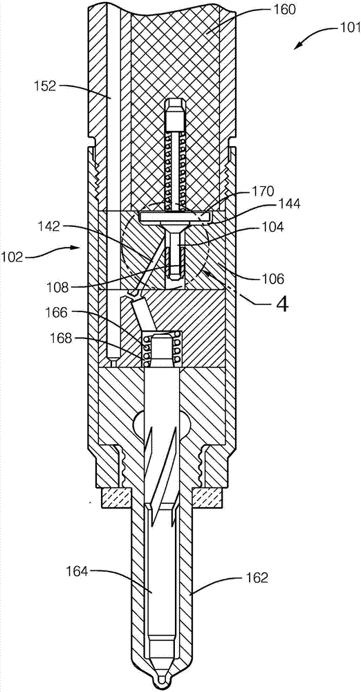
[0023] refer to image 3 with Figure 4 , the injector 101 includes an injector body 160 , an injector nozzle 162 , a movably mounted injector needle 164 , and a control valve assembly 102 .
[0024] The injector 101 has a longitudinal axis A; with respect to the longitudinal axis A references to "axial" and "radial" are made below.
[0025] A spring 166 is disposed in the spring chamber 168 to bias the injector needle 164 toward a seated position in which fuel is prevented from being combusted via one or more spray holes (not shown) provided in the injector nozzle 162. A chamber (not shown) is injected. Under the control of the control valve assembly 102, the injector needle 164 can be moved to an open position wherein fuel can be injected through the spray orifice.
[0026] The control valve assembly 102 of the...
PUM
 Abstract
Description
Claims
Application Information
 - R&D Engineer
- R&D Manager
- IP Professional
- Industry Leading Data Capabilities
- Powerful AI technology
- Patent DNA Extraction
Browse by: Latest US Patents, China's latest patents, Technical Efficacy Thesaurus, Application Domain, Technology Topic, Popular Technical Reports.
© 2024 PatSnap. All rights reserved.Legal|Privacy policy|Modern Slavery Act Transparency Statement|Sitemap|About US| Contact US: help@patsnap.com