
Testing device and testing method for photon upconverter frequency response

A technology of frequency response and testing equipment, which is applied in the direction of measuring equipment, instruments, measuring electronics, etc., to achieve the effect of simple structure, low cost and easy operation

Inactive Publication Date: 2014-09-03
INST OF SEMICONDUCTORS - CHINESE ACAD OF SCI
View PDF2 Cites 2 Cited by
  • Summary
  • Abstract
  • Description
  • Claims
  • Application Information

AI Technical Summary

Problems solved by technology

However, there is currently no method and system for testing the frequency response characteristics of such photonic up-conversion devices

Method used


Image

  • Testing device and testing method for photon upconverter frequency response
  • Testing device and testing method for photon upconverter frequency response
  • Testing device and testing method for photon upconverter frequency response

Examples


Embodiment Construction

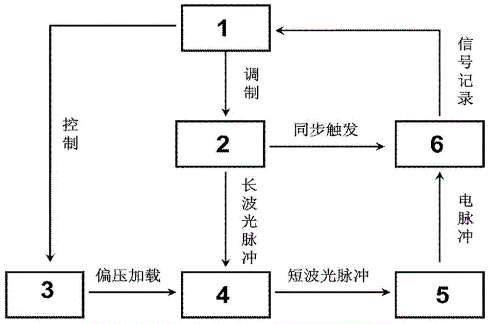
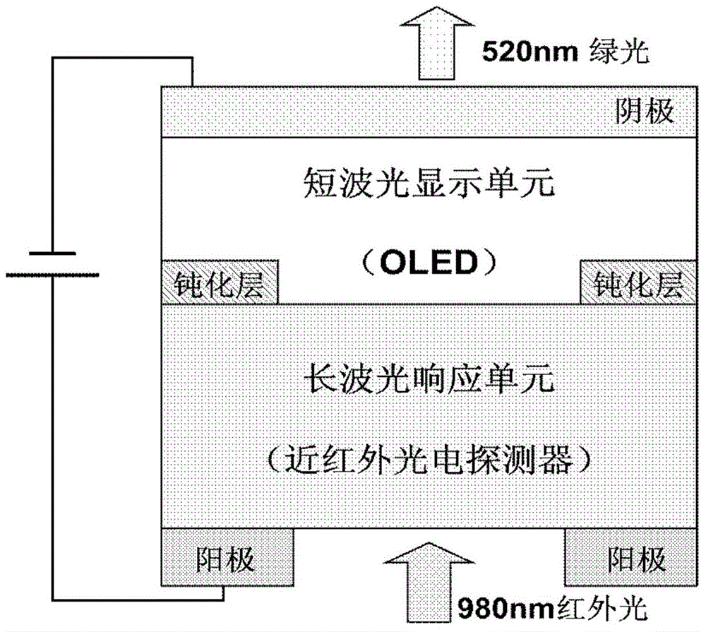
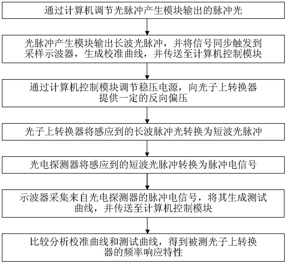
[0029] see figure 1 , figure 2 As shown, the present invention provides a test device for the frequency response of a photon up-converter, comprising:

[0030] A computer control module 1;

[0031] An optical pulse generating module 2, whose input end is connected with an output end of the computer control module 1, said optical pulse generating module 2 is obtained by an electric pulse generator and a laser in series through a radio frequency connection line, or by a pulse The laser is obtained; the frequency, pulse width, waveform, and intensity of the pulsed light signal sent by the optical pulse generation module 2 are modulated by the computer control module 1; The response frequency of the sub-upconverter 4 matches, that is, the wavelength of the pulsed optical signal sent by the optical pulse generating module 2 is within the response wavelength range of the photon upconverter 4;

[0032] A regulated power supply 3, whose input end is connected to the other output e...


PUM


Abstract

A testing device for a photon upconverter frequency response comprises a computer control module, an optical pulse generating module, a voltage-stabilized source, a photon upconverter, a photoelectric detector and a sampling oscilloscope. The input end of the optical pulse generating module is connected with one output end of the computer control module. The input end of the voltage-stabilized source is connected with the other output end of the computer control module. One input end of the photon upconverter is connected with the output end of the voltage-stabilized source. An optical response area of the photoelectric detector receives the optical output signals of the photon upconverter. One input end of the sampling oscilloscope is connected with the output end of the photoelectric detector, the other input end of the sampling oscilloscope is connected with the other output end of the optical pulse generating module, and the output end of the sampling oscilloscope is connected with the input end of the computer control module. According to the device, the frequency response characteristics of photon upconverters of the series can be detected and analyzed, a detecting means and an analysis tool are provided for manufacturing of a photon upconverter with higher response speed, and a foundation is laid for the study of a high-speed infrared imaging device. The invention further provides a testing method for the photon upconverter frequency response.

Description

technical field [0001] The invention relates to the measurement field of optoelectronic devices, in particular to a test device and a test method for the frequency response of a photon up-converter. Background technique [0002] The traditional infrared imager or infrared focal plane device is a detector focal plane array composed of thousands of infrared detector units. Its principle is to convert infrared radiation signals into electrical signals, and the electrical signals pass through the same number of readout The circuit unit is read out and amplified, and finally becomes an image visible to human eyes through subsequent electronic processing. The entire preparation process requires the growth of indium pillars for flip-chip interconnection, and also requires complex readout imaging circuits, resulting in the disadvantages of complex preparation process, low reliability, and high cost. [0003] Photon up-conversion technology refers to the technology of using certain ...

Claims


Application Information

Patent Timeline
IPC IPC(8): G01R31/00
Inventor 楚新波关敏牛立涛李戈洋曾一平
Owner INST OF SEMICONDUCTORS - CHINESE ACAD OF SCI
Learn More