Heat insulation pipe joint structure

A technology of joint structure and thermal insulation pipe, applied in the direction of pipe/pipe joint/pipe fitting, pipeline protection through thermal insulation, pipeline protection, etc., can solve the problems of medium leakage, unable to guarantee the sealing effect, pipe joint falling off, etc., to improve the service life , good sealing and thermal insulation effect, and the effect of ensuring installation reliability

Inactive Publication Date: 2014-09-03
王向林
View PDF9 Cites 4 Cited by
  • Summary
  • Abstract
  • Description
  • Claims
  • Application Information

AI Technical Summary

Problems solved by technology

[0003] The existing treatment method is to put a thermal insulation sleeve on the outside of the joint of the pipeline, and conduct heat insulation treatment on the joint through the thermal insulation sleeve. This method cannot guarantee the sealing effect and seriously affects the use of the thermal insulation pipe network.
[0004] In addition, the reliability of the pipe joints is poor. When the pipes vibrate, it is easy to cause the pipe joints to fall off, resulting in the leakage of the medium

Method used


Image

  • Heat insulation pipe joint structure
  • Heat insulation pipe joint structure
  • Heat insulation pipe joint structure

Examples


Embodiment 1

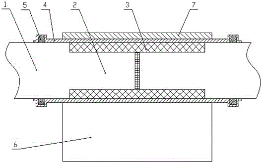
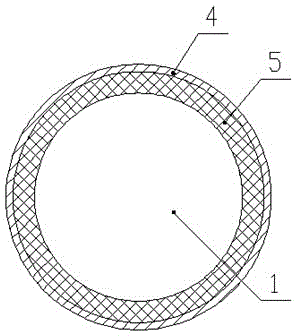
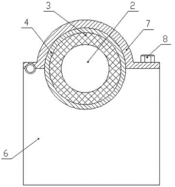
[0028] This embodiment provides a support structure for heat insulating pipe joints, such as Figures 1 to 3 As shown, the two insulated pipes both include a regular section 1 and a joint section 2 at the end of the regular section 1 , and the outer diameter of the joint section 2 is smaller than the outer diameter of the regular section 1 . The two heat-insulating pipes are butted through the joint section 2 and the outer periphery of the butt joint is covered with a heat-insulating sleeve 3 , and the outer peripheral surface of the heat-insulating sleeve 3 is flush with the outer peripheral surface of the conventional section 1 .

[0029] As a preferred manner, the two joint segments 2 are butted by coaxial welding.

[0030] As a preferred manner, the thermal insulation cover 3 is a polyurethane foam layer.

[0031] The outer circumference of the heat insulating sleeve 3 is covered with a sealing collar 4, the length of the sealing collar 4 is greater than the length of the...


PUM


Abstract

The invention discloses a heat insulation pipe joint structure and relates to the technical field of pipe joints, and the heat insulation pipe joint structure can be used for solving the problems that the existing heat insulation pipe joint is poor in heat insulation effect, unreliable in structure and the like. According to the heat insulation pipe joint structure provided by the invention, a sealing sleeve ring is sleeved at the periphery of a heat insulation sleeve; sealing pieces are arranged between two ends of the sealing sleeve ring and the conventional section of a heat insulation pipe; the two sealing pieces are respectively positioned on two sides of the heat insulation sleeve, so that secondary heat insulation is formed at a butted part of the heat insulation pipe due to the sealing pieces, and the sealing and heat insulation effects are good. The joint part of the heat insulation pipe is arranged on a supporting seat, so that the reliability of the joint part of the heat insulation pipe is guaranteed; a semicircular slot is formed in the supporting seat; a clamping hoop is also arranged on the supporting seat; the joint part of the heat insulation pipe is fixedly arranged on the supporting seat by virtue of the clamping hoop; the clamping hoop can limit the radial motion of the joint of the heat insulation pipe; the joint of the heat insulation pipe can do axial micro motion in a containing space formed between the clamping hoop and the semicircular slot, so that the mounting reliability of the joint of the heat insulation pipe is guaranteed.

Description

technical field [0001] The invention relates to the technical field of pipe joints, in particular to a heat insulating pipe joint structure. Background technique [0002] In the fields of heating, cooling, oil and gas pipeline transportation, etc., in order to ensure the heat insulation of the medium in the pipeline, it is necessary to insulate the pipeline. The usual way to deal with insulated pipelines is to process the required insulated pipelines according to the length first, then install them on site, and form joints at the joints of two sections of insulated pipelines. In the insulation pipe network, the quality of the pipe joints and the quality of the insulation treatment will have a great impact on the use of the entire insulation pipe network. [0003] The existing treatment method is to put a heat-insulating sleeve on the outside of the joint of the pipeline, and perform heat-insulation treatment on the joint through the heat-insulating sleeve. This method canno...

Claims


Application Information

Patent Timeline
Patent Type & Authority Applications(China)
IPC IPC(8): F16L21/08F16L59/02
CPCF16L59/182F16L59/024F16L59/028F16L59/135
Inventor 王向林
Owner 王向林
Why Eureka
Try Eureka