Automotive Fuel Emission Reducer
A technology for automobiles and fuel oil, which is applied in the direction of machines/engines, internal combustion piston engines, engine components, etc., and can solve problems such as filter burning, lowering, and filter rupture
- Summary
- Abstract
- Description
- Claims
- Application Information
AI Technical Summary
Problems solved by technology
Method used
Image
Examples
Embodiment 1
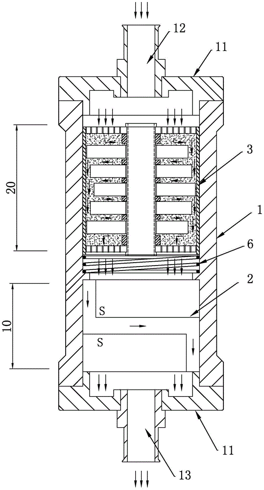
[0041] Such as figure 1 As shown, a strong catalytic zone 20 and a strong magnetic zone 10 are provided in the inner cavity of the housing 1 .
[0042] The strong catalytic area 20 is connected to the oil inlet 12 , the strong magnetic area 10 is placed under the strong catalytic area 20 , and a compression spring 6 is arranged between the strong catalytic area 20 and the strong magnetic area 10 .
[0043] 1. Powerful catalytic zone 20
[0044] Such as Figure 4 , 5 As shown, a fuel catalytic assembly 3 is provided in the strong catalytic zone 20, and the assembly is made of an inner cylinder 31 made of copper, a screen mesh 32 woven with copper, a fastening guide post 33, a plurality of magnetic ring sheets 4 and an inner cylinder full of 31 nanometer 9 material in the cavity cavity (C e o 2 particles) composition.
[0045] The inner cylinder 31 is a hollow cylinder, which is arranged coaxially with the outer shell 1 , and its outer wall is in close contact with the inn...
Embodiment 2
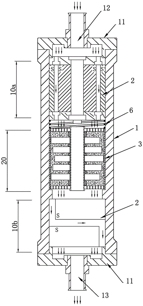
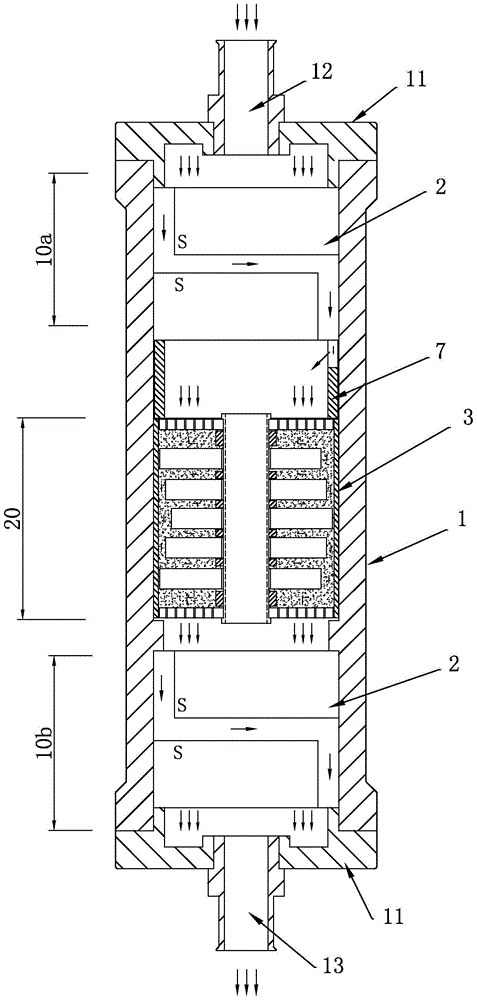
[0075] Such as figure 2 , 3 As shown, the difference between this embodiment and Embodiment 1 is that in the inner cavity of the housing 1, a strong catalytic zone 20 and two strong magnetic zones 10 are provided, and the two strong magnetic zones 10 are respectively connected to the oil inlet 12. The first strong magnetic zone 10a connected to the oil outlet 13 is connected to the second strong magnetic zone 10b, and the strong catalytic zone 20 is placed between the first strong magnetic zone 10a and the second strong magnetic zone 10b.
[0076] The composition and function of the strong magnetic assembly 2 in each strong magnetic area 10 and the fuel catalytic assembly 3 in the strong catalytic area 20 are the same as those in Embodiment 1.
[0077] 1) In this embodiment, when the ferromagnetic assembly 2 in the first ferromagnetic region 10a is the structure of the inner magnet 21 and the outer magnet 22, an oil guide is provided between the first ferromagnetic region 10...
PUM
 Abstract
Description
Claims
Application Information
 - R&D
- Intellectual Property
- Life Sciences
- Materials
- Tech Scout
- Unparalleled Data Quality
- Higher Quality Content
- 60% Fewer Hallucinations
Browse by: Latest US Patents, China's latest patents, Technical Efficacy Thesaurus, Application Domain, Technology Topic, Popular Technical Reports.
© 2025 PatSnap. All rights reserved.Legal|Privacy policy|Modern Slavery Act Transparency Statement|Sitemap|About US| Contact US: help@patsnap.com


