
Oil-saving emission-reduction device for automobile

A technology for automobiles and fuels, used in machines/engines, internal combustion piston engines, engine components, etc., to solve problems such as filter burnout, emission reduction, filter rupture, etc.

Active Publication Date: 2014-09-03
苏悦熙
View PDF7 Cites 4 Cited by
  • Summary
  • Abstract
  • Description
  • Claims
  • Application Information

AI Technical Summary

Problems solved by technology

The main cause of damage is that the temperature rises too fast and the filter ruptures
If the exhaust temperature is too low, it is not easy to catalyze and cause blockage; while the exhaust temperature is too high (according to relevant data records: when the temperature is greater than 1000 ° C), it is easy to cause the filter to burn
[0010] With the continuous development of science and technology, advanced technologies such as high-pressure injection, high-pressure common rail, electronic control, and supercharged intercooling have been adopted for gasoline and diesel engines, and fuel consumption has been reduced to a certain extent. CO, HC (carbonization) in emissions Hydrogen) content has also improved, but this way of creating a good mixture of oil and gas with high pressure injection is not conducive to NO X (nitrogen oxides) and PM particulate emissions reduction

Method used


Image

  • Oil-saving emission-reduction device for automobile
  • Oil-saving emission-reduction device for automobile
  • Oil-saving emission-reduction device for automobile

Examples


Embodiment 1

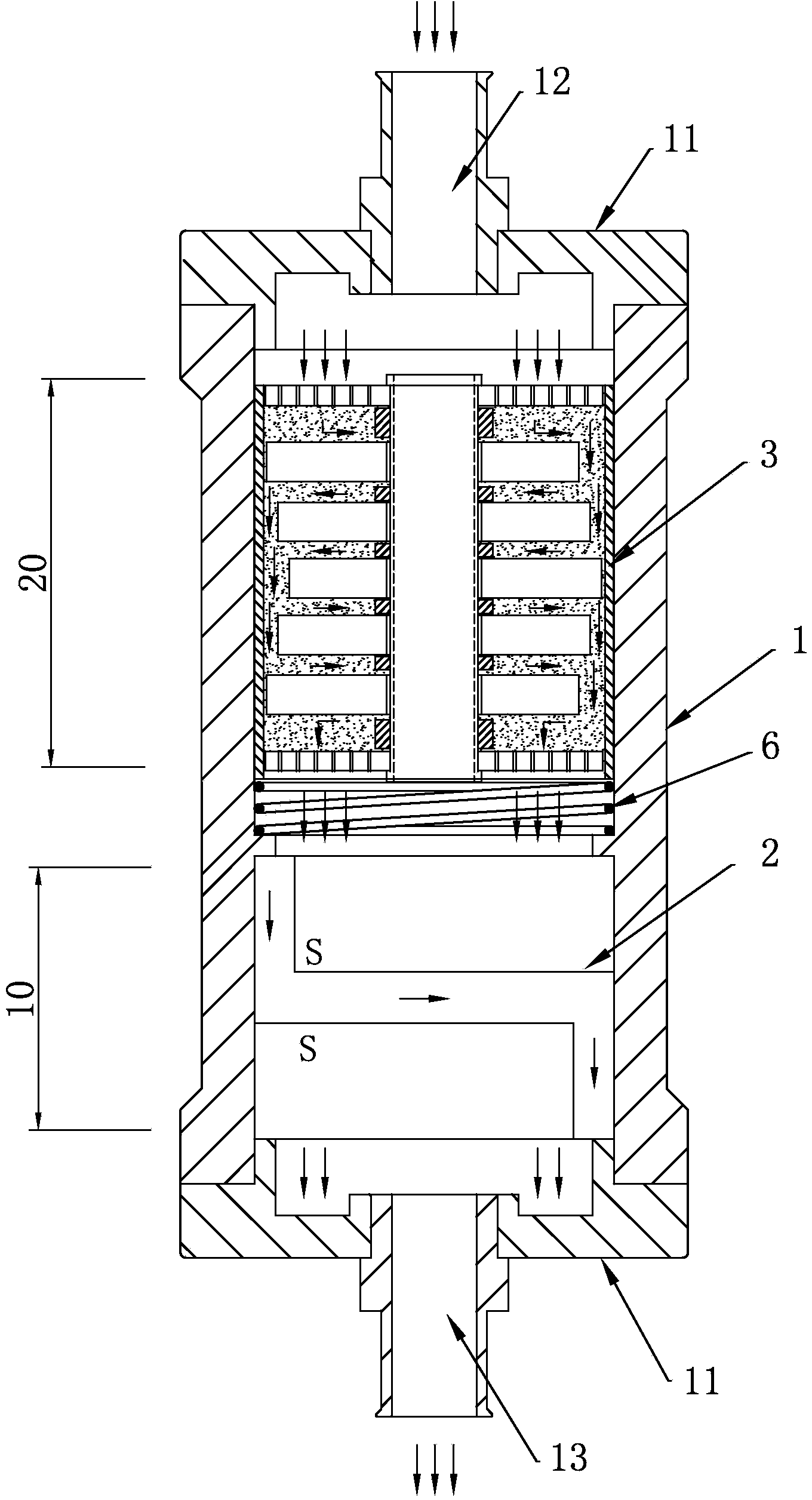
[0041] Such as figure 1 As shown, a strong catalytic zone 20 and a strong magnetic zone 10 are provided in the inner cavity of the housing 1 .

[0042] The strong catalytic area 20 is connected to the oil inlet 12 , the strong magnetic area 10 is placed under the strong catalytic area 20 , and a compression spring 6 is arranged between the strong catalytic area 20 and the strong magnetic area 10 .

[0043] 1. Powerful catalytic zone 20

[0044] Such as Figure 4 , 5 As shown, a fuel catalytic assembly 3 is provided in the powerful catalytic zone 20, the assembly is made of an inner cylinder 31 made of copper, a 250-350 mesh copper woven screen 32, a fastening guide post 33, and a plurality of magnetic ring pieces 4 And be filled with the nanometer 9 material (C e o 2 particles) composition.

[0045] The inner cylinder 31 is a hollow cylinder, which is arranged coaxially with the outer shell 1 , and its outer wall is in close contact with the inner wall of the outer shell...

Embodiment 2

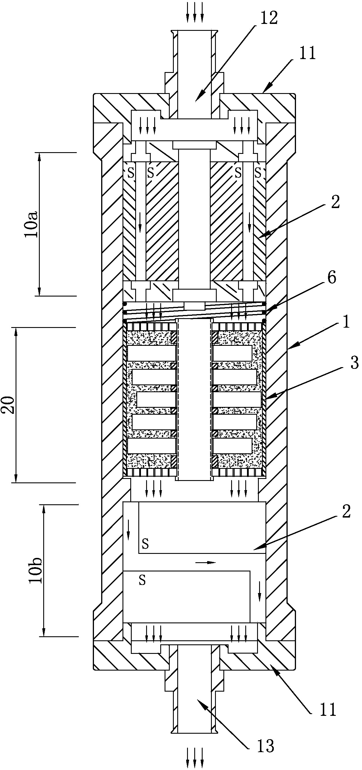
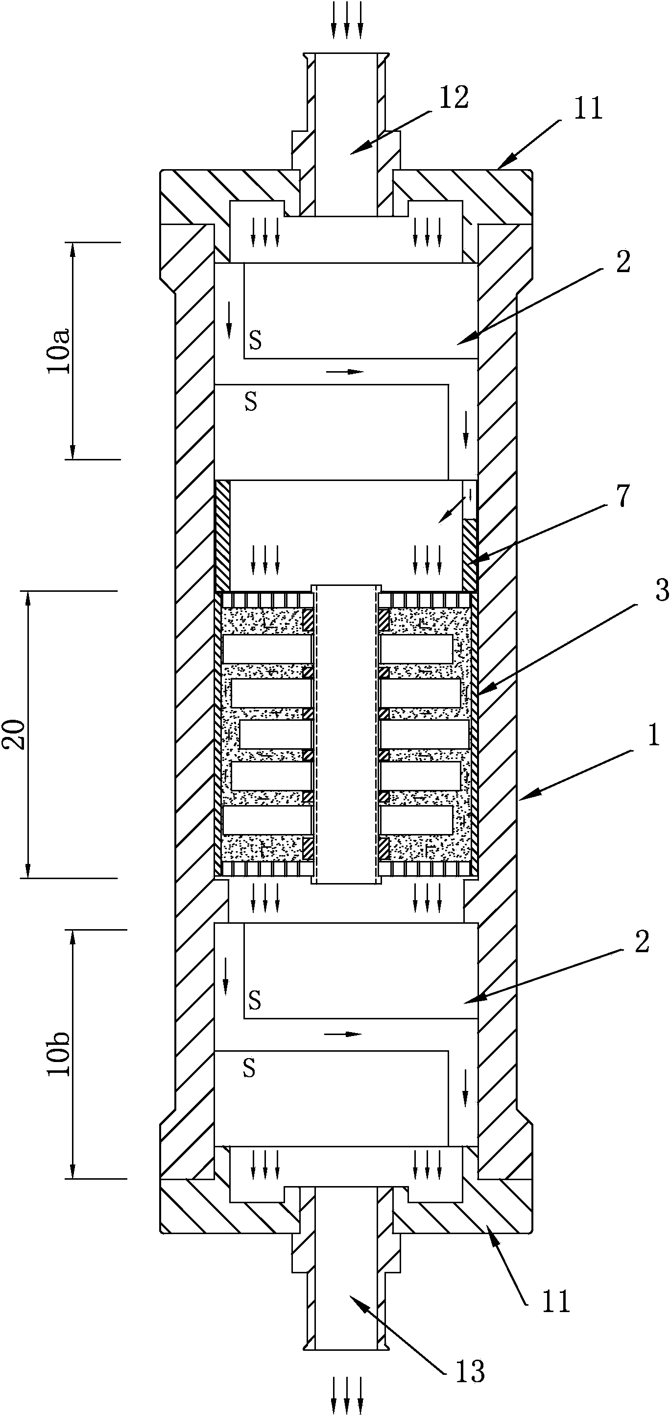
[0075] Such as figure 2 , 3 As shown, the difference between this embodiment and Embodiment 1 is that in the inner cavity of the housing 1, a strong catalytic zone 20 and two strong magnetic zones 10 are provided, and the two strong magnetic zones 10 are respectively connected to the oil inlet 12. The first strong magnetic zone 10a connected to the oil outlet 13 is connected to the second strong magnetic zone 10b, and the strong catalytic zone 20 is placed between the first strong magnetic zone 10a and the second strong magnetic zone 10b.

[0076] The composition and function of the strong magnetic assembly 2 in each strong magnetic area 10 and the fuel catalytic assembly 3 in the strong catalytic area 20 are the same as those in Embodiment 1.

[0077] 1) In this embodiment, when the ferromagnetic assembly 2 in the first ferromagnetic region 10a is the structure of the inner magnet 21 and the outer magnet 22, an oil guide is provided between the first ferromagnetic region 10...


PUM


Abstract

The invention discloses an oil-saving emission-reduction device for an automobile. The strong magnetic and nuclear magnetic resonance principle is utilized to change the activity of fuel, the rare earth catalyzing effect is improved to improve the fuel utilization rate and reduce pollutant emission. The oil-saving emission-reduction device for the automobile comprises a shell made of a non-permeability-magnetic material. A strong magnetic area and a strong catalyzing area are arranged in an inner cavity of the shell, wherein the fuel can pass through the strong magnetic area and a strong catalyzing area. Two magnetic parts with magnetic poles of the same polarity facing to each other are arranged in the strong magnetic area, the magnetic inductive strength of the surfaces of the magnetic parts ranges from 0.34T to 0.38T, and the fuel flows through a gap between the two magnetic parts. A fuel catalyzing assembly through which the fuel passes is arranged in the strong catalyzing area, wherein the magnetic sheets and a nanometer material are arranged in the fuel catalyzing assembly. The oil-saving emission-reduction device for the automobile conducts at least one time of strong magnetization and one time of strong catalytic activation on the fuel flowing through the oil-saving emission-reduction device, after the fuel leaves a magnetic field, binding force of the fuel is reduced, intermolecular interaction force is also reduced, and little increment of the intermolecular distance will greatly reduce intermolecular cohesion force. The oil-saving emission-reduction device for the automobile can enable the fuel to be sufficiently combusted, improve the fuel utilization rate and greatly reduce emission of waste gas.

Description

technical field [0001] The invention relates to an energy-saving and emission-reducing device for diesel and gasoline vehicles, in particular to an automobile fuel-saving and emission-reducing device using magnetized components for energy saving. Background technique [0002] 1. Motivation for invention and creation: [0003] According to statistics, by 2012, the number of motor vehicles in the country was 233 million, of which, the number of gasoline engine vehicles was 114 million, and the number of diesel engine vehicles was 119 million, with an annual growth rate of no less than 7%. [0004] For most of these gasoline and diesel vehicles, due to technical reasons, the fuel consumption rate and pollutant emissions are not up to GB18352.3XⅡ2005 "Light Vehicle Pollutant Emission Limits and Measurement Methods" and GB17691-2005 "Vehicle Compression Ignition, Gas Fuel Ignition Engine and Automobile Exhaust Pollutant Emission Limits and Measurement Methods" standard. [0005...

Claims


Application Information

Patent Timeline
Patent Type & Authority Applications(China)
IPC IPC(8): F02M27/02F02M27/04
CPCY02T10/126Y02T10/12
Inventor 苏悦熙
Owner 苏悦熙
Learn More