
Floating body gate and method thereof

A floating body gate and gate technology, applied in hydraulic engineering, marine engineering, coastline protection, etc., can solve problems such as working gates that can only be used as docks or as maintenance gates on ship locks, spillways and sluices, and avoid frequent replacement. , The effect of easy installation and simple structure

Active Publication Date: 2014-09-03
浙江衢州河口闸门有限公司
View PDF4 Cites 29 Cited by
  • Summary
  • Abstract
  • Description
  • Claims
  • Application Information

AI Technical Summary

Problems solved by technology

First of all, in terms of structural form, although the traditional floating box door is divided into square box type, hydrometer type and barrel type, its upper and lower parts are all box-shaped structures, while the lower part of the floating body gate is a floating box, and the upper part of the floating body gate is set. It is a horizontal flat gate structure; the second is the operating conditions. The traditional floating box gate generally can only operate in still water or waters with a small flow rate, that is, sinking and floating in flat water. The floating gate breaks through the limit of use in still water and can be used in still water Ups and downs in moving water rely on its own stability; thirdly, in terms of application range, traditional buoyant gates can usually only be used as working gates in docks or as maintenance gates on ship locks, spillways and sluices

Method used


Image

  • Floating body gate and method thereof
  • Floating body gate and method thereof
  • Floating body gate and method thereof

Examples


Embodiment Construction

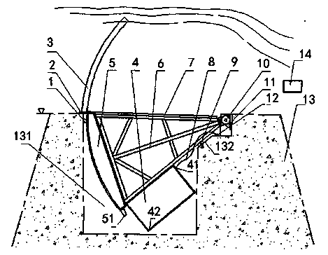
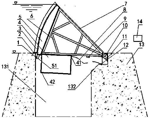
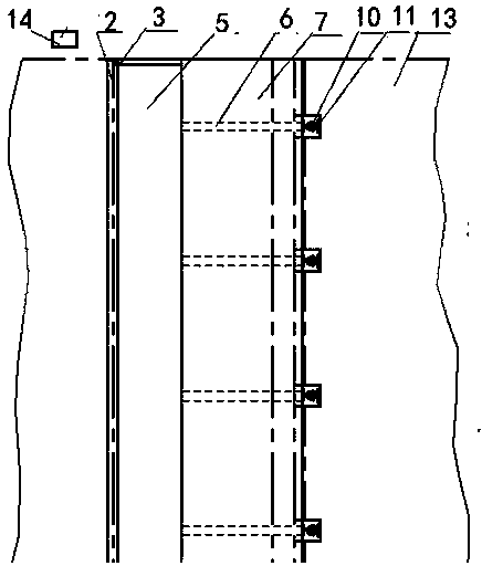
[0016] Such as figure 1 , 2 , 3, the floating body gate is characterized in that it includes a limit block 1, a bottom water-stop rubber 2, a side water-stop rubber 3, a floating body 4, a door leaf 5, a support arm 6, a support arm cover plate 7, a hose 8, a buffer Rubber 9, support shaft 10, support 11, air pipe 12, dam body 13, air compressor 14; the end of the dam body 13 is provided with a limit block 1 and bottom water-stop rubber 2, and the support 11 is fixedly installed on the dam body 13 Above, the support arm 6 is connected to the support 11 through the support shaft 10, the floating body 4 is fixedly installed below the support arm 6, the support arm cover 7 is fixedly installed above the support arm 6, and the back of the door leaf 5 is fixedly connected to the support arm 6 When the gate sinks and floats, the door leaf 5, the floating body 4 and the cover plate 7 of the support arm and the support arm 6 can freely rotate around the support shaft 10. The air inle...


PUM


Abstract

The invention discloses a floating body gate and a method of the floating body gate. The floating body gate comprises a limiting block, bottom water stop rubber, side water stop rubber, a floating body, a door leaf, a support arm, a support arm cover plate, a hose pipe, buffering rubber, a support base shaft, a support base, an air delivery pipe, a dam body and an air compressor. The floating body gate has the basic functions of a common water gate and further has the two advantages that the water gate flowing width is equal to the channel width, no water stop buildings exist above the dam body of a river channel when the gate is opened, and therefore the contradiction between river channel shipping and flood control is solved well; the floating body gate has the ecological function, no vertical stairs exist when the floating body gate is closed for water storage or opened for aerial drainage, so that fishes and river channel objects pass freely, the noise of water flow falling does not exist, and natural features of the river channel are kept. The floating body gate is convenient to transport, maintain and install, simple in structure, low in cost and suitable for water storage or drainage of dams, and has excellent application prospects and obvious technical advantages, and the water stop structure of the gate is stable and effective for a long time so that frequent replacement can be avoided.

Description

technical field [0001] The invention relates to a water storage and flood control gate structure that has high requirements on the ecological environment and can maintain the function of a natural river, in particular to a floating body gate and a method thereof. Background technique [0002] The gate is a kind of water retaining structure, which is used for water storage and discharge of dams. Currently used gates include flap gates, rubber dams, bottom shaft gates, arc gates and other types of gates, each of which has its advantages and disadvantages in implementation. Although the cost of the flap gate is lower, it is easy to get stuck with debris during use, and it is not easy to clean. It is often damaged by debris and difficult to repair. The hydraulic opening and closing system is expensive and difficult to maintain; the rubber dam is easy to age and has a low service life. , easy to be damaged by debris, long repair time, high power consumption during use; althou...

Claims


Application Information

Patent Timeline
IPC IPC(8): E02B7/50E02B7/54
Inventor 张晓敏
Owner 浙江衢州河口闸门有限公司
Learn More