An online turning device for a rubberized drum

A rubber-covered roller and turning technology, which is applied in metal processing and other directions, can solve the problems of increasing labor intensity and workload, redistribution of conveyor belts, and unsafe quality, and achieve reduction of labor intensity and workload, and power imbalance. , to avoid the effect of repeated disassembly and measurement

Active Publication Date: 2015-12-16
SHANDONG KEDA ELECTROMECHANICAL TECH CO LTD
View PDF8 Cites 0 Cited by
  • Summary
  • Abstract
  • Description
  • Claims
  • Application Information

AI Technical Summary

Problems solved by technology

[0003] With the development of science and technology and the improvement of production automation, the belt conveyor is developing in the direction of long distance, large capacity, high power, high speed, bendable, large inclination, multi-motor drive and power monitoring system. , under ideal conditions, the power distribution ratio between the motors is the same as the driving force distribution ratio. However, as the use time increases, the rubber on the rubber drum is easy to wear, and the rubber drum along the entire transportation line does not wear much. First, over time, the thickness of each rubber-coated roller is inconsistent, resulting in a large deviation in the actual power distribution of each motor, which not only causes the redistribution of the tension of the conveyor belt, but also makes the power load of each motor unbalanced. One of the motors is overloaded or even damaged, affecting production
In order to avoid this problem, the current common practice is to stop the belt conveyor after running for a period of time, disassemble the rubberized rollers for measurement, and then turn them to the same thickness before installing them on the conveyor line. This method increases the Labor intensity and workload, and the quality cannot be guaranteed

Method used


Image

  • An online turning device for a rubberized drum
  • An online turning device for a rubberized drum
  • An online turning device for a rubberized drum

Examples


Embodiment Construction

[0023] The present invention will be further described in detail below in conjunction with the accompanying drawings and specific embodiments, but the present invention is not limited to these embodiments.

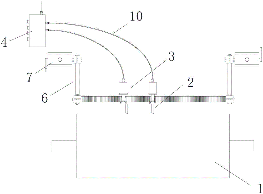
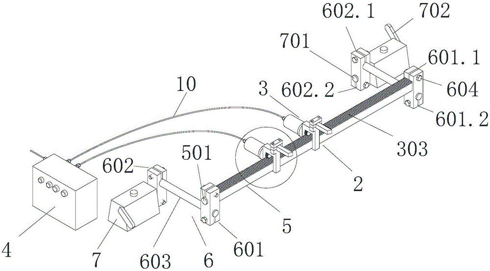
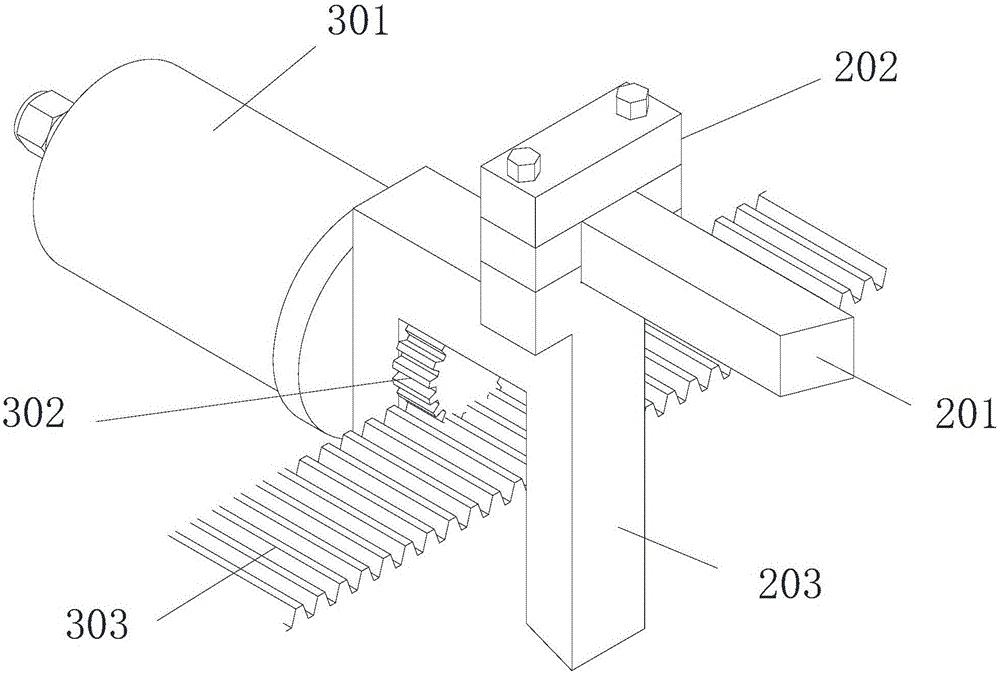
[0024] Such as Figure 2 to Figure 4 As shown, a turning department includes a turning tool assembly 2, a power mechanism 3 that drives the turning tool assembly 2 for turning, and an electric control box 4 for controlling the power mechanism 3. There are two sets of turning tool assemblies 2 , which are respectively nested on the guide rail 5, each turning tool assembly 2 includes a turning tool 201 and a turning tool positioning frame 203 that can slide along the above-mentioned guide rail 5, the turning tool 201 is connected with the turning tool positioning plate 202, and the turning tool positioning plate 202 is arranged on the top of the turning tool positioning frame 203, the plane where the turning tool positioning plate 202 is located is perpendicular to the plane...


PUM


Abstract

The invention discloses a turning part. The turning part comprises a turning tool assembly, a power mechanism driving the turning tool assembly to conduct turning and an electric cabinet used for controlling the power mechanism. The turning tool assembly is arranged on a guide rail in a sleeved mode. The invention further discloses a rubber coated roller on-line turning device. The rubber coated roller on-line turning device comprises a plurality of rubber coated rollers mounted on a belt conveyor conveying line, a rubber coated roller fixing rack and the turning part used for on-line turning of all the rubber coated rollers. The turning part and the rubber coated rollers are installed independently. The two ends of the guide rail are connected with a magnetic base capable of being attracted to the rubber coated roller fixing rack through supports respectively. The rubber coated roller on-line turning device is mainly applied to on-line turning of all the rubber coated rollers on a belt conveyor; the problem that when a multi-drive-belt conveyor is used, since the thicknesses of rubber coating layers of all the rollers are different, the powers of all drivers are imbalanced is solved; repeated disassembly and assembly for measurement of the rubber coated rollers in a conventional turning process is avoided, so that labor intensity is lowered, and production efficiency is improved.

Description

technical field [0001] The invention relates to a turning device, in particular to an online turning device for a turning part and a rubber-covered cylinder. Background technique [0002] In the continuous transportation of modern bulk materials, the belt conveyor is the main transportation equipment. It has a wide range of applications and has the advantages of low transportation cost, large transportation volume, no terrain restrictions and easy maintenance. Enterprises in working conditions such as wharfs are increasingly showing their important role. A general-purpose belt conveyor consists of a conveyor belt, idler rollers, rubber-covered rollers, and devices for driving, braking, tensioning, redirection, loading, unloading, and cleaning. Among them, the rubber-coated roller is an important part of the belt conveyor system. Components and components, the rubber lagging of the pulley can effectively improve the operation of the conveying system, protect the metal pulley...

Claims


Application Information

Patent Timeline
Patent Type & Authority Patents(China)
IPC IPC(8): B26D1/04B26D7/26B26D5/06
Inventor 朱坤海周生朋成祥宁吴广清王希凤
Owner SHANDONG KEDA ELECTROMECHANICAL TECH CO LTD
Why Eureka
Try Eureka