Device and method for detecting deposits

A detection device and sediment technology, applied in the field of detection and analysis of sediment, can solve the problems of distorted measurement results, unfavorable measurement quality, and inaccurate determination of sediment thickness, and achieve the effect of reducing installation costs

Active Publication Date: 2014-08-27
SOLENIS TECH CAYMAN
View PDF6 Cites 4 Cited by
  • Summary
  • Abstract
  • Description
  • Claims
  • Application Information

AI Technical Summary

Problems solved by technology

This is detrimental to the quality of the measurements, since higher temperatures increase the growth of dirt, whereby the accumulation of deposits is often higher inside the functional unit than in the connecting pipes
Consequently, the results of the measurements in the connecting pipes are distorted and the thickness of the deposits on the associated areas cannot be precisely determined

Method used


Image

  • Device and method for detecting deposits
  • Device and method for detecting deposits
  • Device and method for detecting deposits

Examples


Embodiment Construction

[0035] The present invention will be described with respect to particular embodiments and with reference to certain drawings but the invention is not limited thereto but only by the claims. The illustrated figures are only schematic and not limiting. In the drawings, the size of some of the elements may be exaggerated and not drawn on scale for illustrative purposes.

[0036] Where an indefinite or definite article is used when referring to a singular noun, eg "a", "an", "the", this includes a plurality of such nouns unless something else is specifically stated .

[0037] Additionally, the terms first, second, third, etc. in the description and in the claims are used to distinguish similar elements and not necessarily to describe a sequential or chronological order. It is to be understood that the terms so used are interchangeable under appropriate circumstances and that the embodiments of the invention described herein are capable of operation in other sequences than illust...


PUM


Abstract

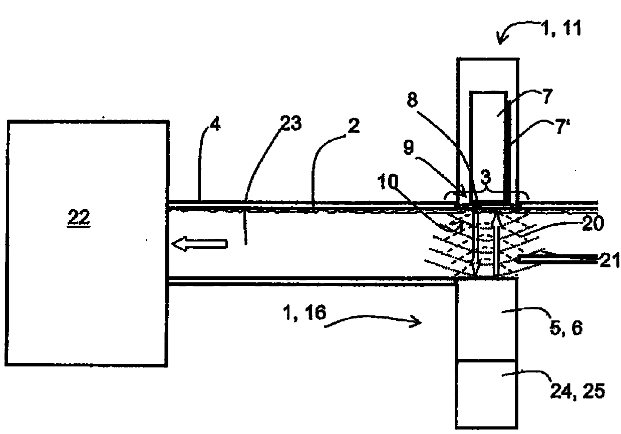
The present invention relates to a device and a method for detecting deposits in a reflecting area inside a liquid-bearing system comprising an ultrasonic transducer for emitting an ultrasonic emission signal towards the reflecting area and a detection means for detecting an ultrasonic reflection signal obtained by reflection of the ultrasonic emission signal in the area of the reflecting area, wherein the device further comprises heating means for increasing the temperature of the reflecting area.

Description

technical field [0001] The present invention relates to devices and methods for detecting and analyzing deposits. Background technique [0002] Industrial plants such as power plants, steel mills, pulp or paper mills, etc. often include devices for conducting or storing fluids, such as pipelines or fluid containers. It is a known problem that organic and inorganic substances deposit on the inner walls of these devices for guiding or storing fluid, whereby the accumulation of dirt or scale deposits at least partially blocks the flow through the guiding device and is guided or Stored fluid may become contaminated. This is an undesirable occurrence that causes numerous operational problems such as clogging of equipment, inefficient use of chemicals, increased cost of use, loss of production due to downtime, corrosion, and increased levels of fouling due to resulting in product degradation. [0003] In principle, a person can distinguish between fouling deposits on the one ha...

Claims


Application Information

Patent Timeline
Patent Type & Authority Applications(China)
IPC IPC(8): G01N17/00G01N29/00
CPCG01N2291/2636G01B17/02G01N2291/0237G01N2291/0289G01N17/008G01N2291/044G01N2291/101G01N29/00G01N2291/045G01N29/44G01N2291/0231G01N29/043
Inventor F·赛德C·弗洛肯P·比尔甘斯M·舒尔茨
Owner SOLENIS TECH CAYMAN
Why Eureka
Try Eureka