
Shot peening device and shot peening method

A technology of shot peening and spray chamber, which is applied in the field of shot peening devices, can solve problems such as poor operability and increased burden on staff, and achieve the effect of reducing time and improving operability

Active Publication Date: 2014-08-27
SINTOKOGIO LTD
View PDF9 Cites 2 Cited by
  • Summary
  • Abstract
  • Description
  • Claims
  • Application Information

AI Technical Summary

Problems solved by technology

[0003] However, in order to carry the workpiece into the blasting chamber provided in the shot blasting processing device, in the shot blasting processing device for the worker to load and unload the workpiece, if the height of the workbench for fixing the workpiece is not set as the height of the worker If the height is easy to work, there is a problem that the operability is poor and the burden on the staff increases

Method used


Image

  • Shot peening device and shot peening method
  • Shot peening device and shot peening method
  • Shot peening device and shot peening method

Examples


Embodiment Construction

[0033] (Shot blasting device)

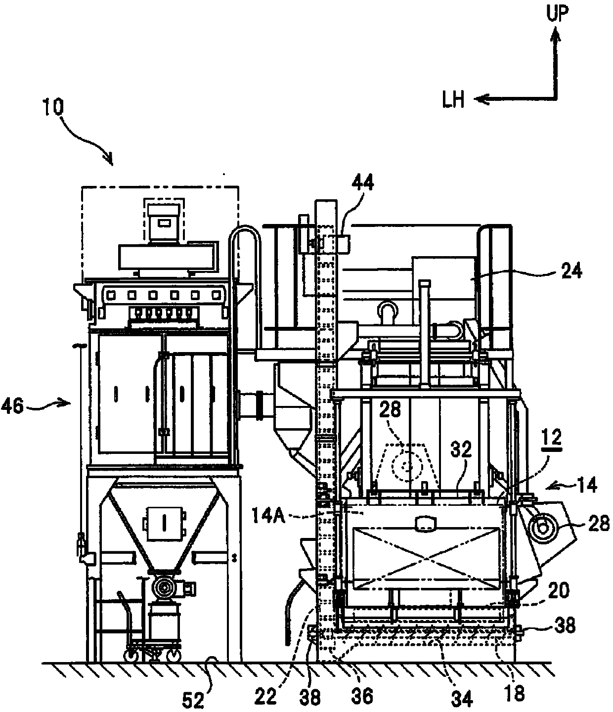
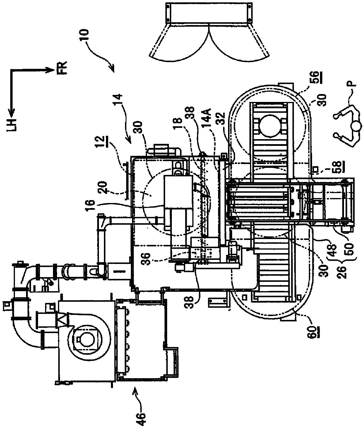
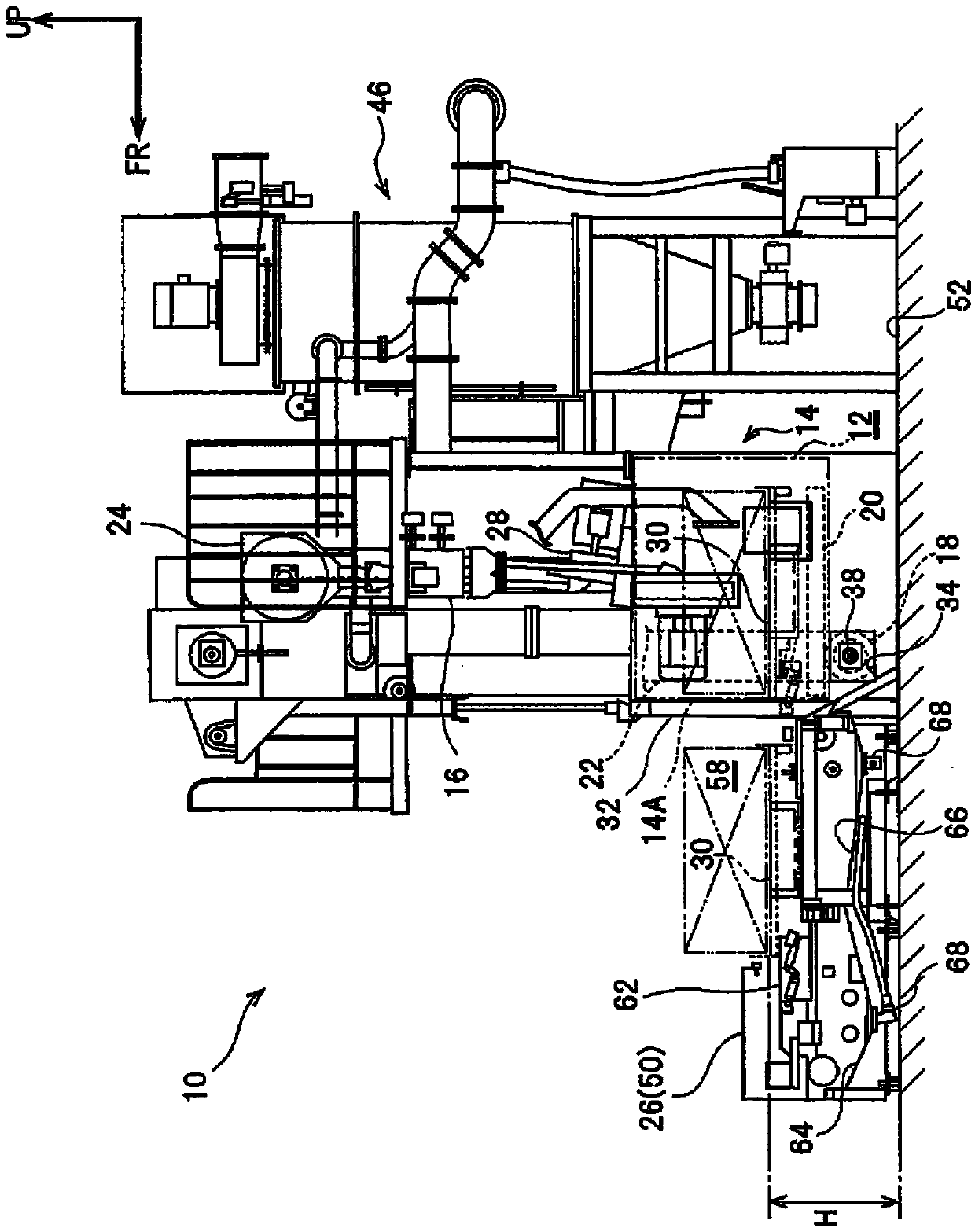
[0034] use Figure 1 ~ Figure 4 The shot blasting apparatus which is a shot blasting apparatus which concerns on embodiment of this invention is demonstrated. Among them, the arrow FR appropriately shown in the above drawings indicates the front side (near side) in the front-rear direction when the device is viewed from the front, the arrow UP indicates the upper side of the device, and the arrow LH indicates the left side when the device is viewed from the front. . In addition, in the following description, when the directions of front and rear, up and down, and left and right are used unless otherwise specified, they mean front and rear in the front and rear direction of the device, up and down in the up and down direction of the device, and left and right in the left and right direction of the device.

[0035] like figure 1 As shown, the shot blasting device 10 as the shot blasting processing device according to the present embodiment incl...


PUM


Abstract

Provide are a shot peening device and a shot peening method that are capable of improving the workability of workpiece placement and removal. The shot blasting device (10) is provided with: a cabinet (14), which is equipped therein with a projection chamber (12) in which a shot medium is projected at the workpiece and in which a workpiece conveyance inlet / outlet (14A) is provided in the side wall of the projection chamber; a screw conveyor (18), which conveys shot medium, which has fallen into the lower section of the projection chamber, in a prescribed direction; and a bucket elevator (22) that is disposed on the same axis as the screw conveyor and conveys shot medium, which has been transported by the screw conveyor, in the height direction of the device.

Description

technical field [0001] The present invention relates to a shot peening device and a shot peening method for spraying a shot material onto a workpiece. Background technique [0002] In the past, there are known a shot peening device and a shot peening method in which a workpiece is carried into a blasting chamber provided in the shot blasting device and sprays a blasting material to the workpiece in the blasting chamber (for example, refer to Japanese Patent Application Laid-Open No. 2002-96264 ). [0003] However, in order to carry the workpiece into the blasting chamber provided in the shot blasting processing device, in the shot blasting processing device for the worker to load and unload the workpiece, if the height of the workbench for fixing the workpiece is not set as the height of the worker At a height that is easy to work, there is a problem that operability is poor and the burden on workers increases. Contents of the invention [0004] This invention considers ...

Claims


Application Information

Patent Timeline
Patent Type & Authority Applications(China)
IPC IPC(8): B24C9/00B24C3/18
CPCB24C1/10
Inventor 山本万俊
Owner SINTOKOGIO LTD
Learn More