
Self-interference canceling circuit

A self-interference elimination and circuit technology, which is applied in the direction of electrical components, recording carriers used by machines, instruments, etc., can solve the problems of limited number of tags, short reading and writing distance of electronic tags, and low receiving sensitivity of passive RFID systems, and achieve improved The effect of receiving sensitivity, increasing the number of tags, and strengthening the ability to read and write

Active Publication Date: 2014-08-27
BEIJING UNIV OF POSTS & TELECOMM
View PDF5 Cites 19 Cited by
  • Summary
  • Abstract
  • Description
  • Claims
  • Application Information

AI Technical Summary

Problems solved by technology

The reasons for the above two problems are as follows: First, the passive electronic tag itself does not provide energy. The energy for the tag to work comes from the electromagnetic wave reflected by the reader. The reflected signal of the tag is only 20% of the received electromagnetic wave energy, which is very weak; For the reader, the reader used in the passive RFID system adopts the communication method of sending and receiving at the same time and at the same frequency.
Therefore, for passive RFID systems, the isolation between the reader's transmission path and the reception path will affect the receiving sensitivity of the overall system.
In the prior art, the realization of passive RFID system transceiver isolation mainly adopts a circulator or a directional coupler (also known as a "transmitter isolation module"). In the case of matching of all ports, the isolation degree of the "transmitter isolation module" is 20 ~30dB, so the power leaked from the transmitting path to the receiving path (that is, the main "self-interference" signal power) is much greater than the signal power reflected back by the electronic tag, which makes the receiving sensitivity of the entire passive RFID system become quite low. Ultimately, the reading and writing distance of the electronic tag is short, and the number of recognized tags is limited
Second, there are two other sources of the self-interference signal mentioned above, one part is from the impedance mismatch at the antenna end. When the transmission channel transmits the modulated signal, there will be an interference signal formed by reflected standing waves into the receiving channel; The other part is the transmitted modulated signal. After being reflected by the environment around the label, it enters the receiving channel with the reflected signal of the label. These two self-interference signals will also affect the receiving sensitivity of the system.
Third, in the prior art, the antenna end (remote end) of many readers adopts the structure of distributed antenna. , these transmission media will have an attenuation effect on the signal when transmitting the signal. The tag reflection signal in the uplink signal will be greatly attenuated and will be submerged in the noise, thus affecting the receiving sensitivity of the back-end reader. Therefore, It is particularly important to eliminate self-interference signals and increase the amplitude of tag reflection signals

Method used


Image

  • Self-interference canceling circuit
  • Self-interference canceling circuit
  • Self-interference canceling circuit

Examples


Embodiment Construction

[0039] Embodiments of the present invention will be further described in detail below in conjunction with the accompanying drawings and examples. The following examples are used to illustrate the present invention, but should not be used to limit the scope of the present invention.

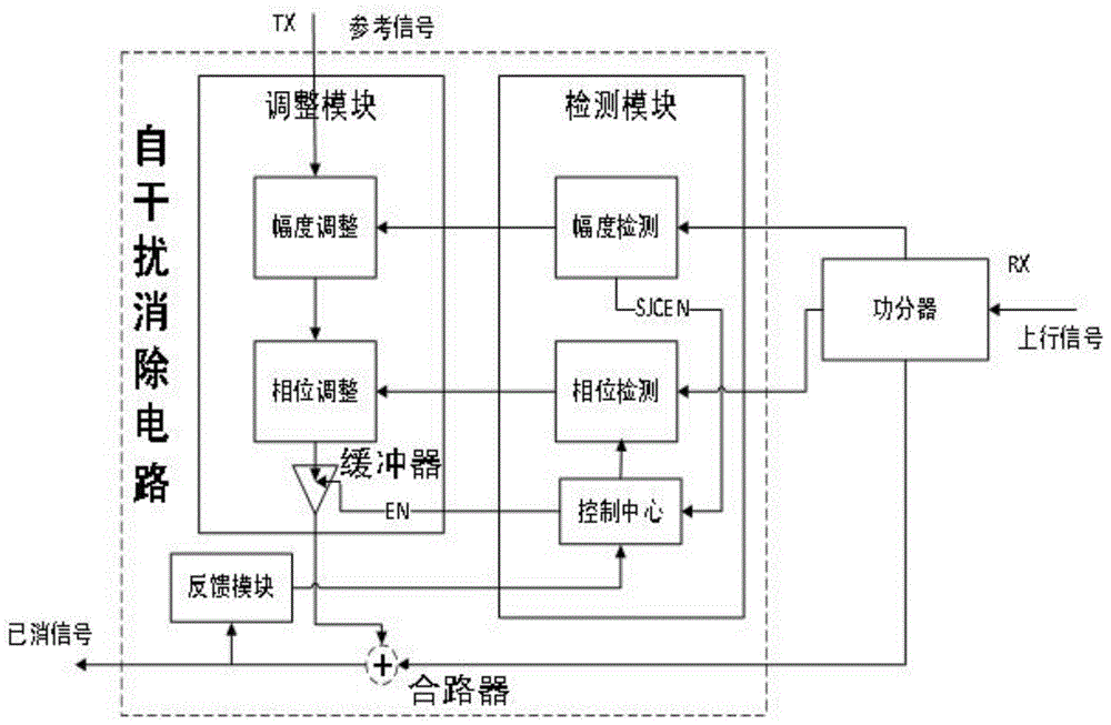
[0040] like figure 1As shown, the traditional full-scale method of self-interference cancellation does not estimate the size of the uplink signal. The system just adds a fixed-sized cancellation signal to the uplink signal. The cancellation signal is adjusted and reversed according to a part of the downlink signal. formed after phase adjustment. This kind of self-interference cancellation circuit, no matter how big the self-interference signal is, the self-interference cancellation circuit can only eliminate the self-interference signal of a fixed size, it can only suppress the carrier leakage signal with relatively stable amplitude and phase, and cannot suppress the signal parameters at all. Th...


PUM


Abstract

The invention relates to a self-interference canceling circuit comprising a detection module, an adjustment module, a feedback module and a combiner. By the adoption of the structure, the read-write capacity of electronic tags is enhanced, the number of identified tags is increased, the receiving flexibility of the system is improved, the amplitude of reflected signals of the tags is increased, and therefore a series of disadvantages caused by the self-interference problem in a passive RFID system are solved. The self-interference canceling circuit can be applied to various fields such as warehouse management in logistic storage, identity recognition, traffic and transportation, food, medical treatment, animal management, entrance guard burglary prevention and military industry.

Description

technical field [0001] The invention relates to a self-interference elimination circuit, in particular to a self-interference elimination circuit in a passive RFID system. Background technique [0002] Radio Frequency Identification (RFID) is a non-contact automatic identification technology. Its basic principle is to use radio frequency signals and spatial coupling transmission characteristics to automatically identify target objects and obtain relevant information to achieve automatic identification. RFID technology has a very wide range of application prospects, and more and more people pay more and more attention to it. It can be used in various fields such as warehouse management, identification, transportation, food and medical care, animal management, access control, and industrial military in logistics and warehousing. People's lives have brought great convenience. [0003] Passive radio frequency identification system is the mainstream of RFID technology applicatio...

Claims


Application Information

Patent Timeline
IPC IPC(8): G06K19/077H04B1/52
Inventor 徐坤肖阳李建强戴一堂尹飞飞
Owner BEIJING UNIV OF POSTS & TELECOMM
Learn More