
Signal frequency real-time measuring method based on low-frequency square signal frequency prediction

A technology of signal frequency and low frequency square wave, applied in the field of real-time measurement of signal frequency

Inactive Publication Date: 2014-08-27
SOUTHWEST UNIVERSITY
View PDF12 Cites 3 Cited by
  • Summary
  • Abstract
  • Description
  • Claims
  • Application Information

AI Technical Summary

Problems solved by technology

[0004] The purpose of the present invention is to propose a more real-time and accurate method for measuring the frequency of low-frequency square wave signals, which can compensate for the hysteresis error existing in the existing cycle measurement method, and can be used for equipment with low-frequency signal frequency measurement functions such as frequency meters and tachometers.

Method used


Image

  • Signal frequency real-time measuring method based on low-frequency square signal frequency prediction
  • Signal frequency real-time measuring method based on low-frequency square signal frequency prediction
  • Signal frequency real-time measuring method based on low-frequency square signal frequency prediction

Examples


Embodiment Construction

[0042] The present invention will be further described below in conjunction with drawings and embodiments.

[0043] Linear fit prediction method:

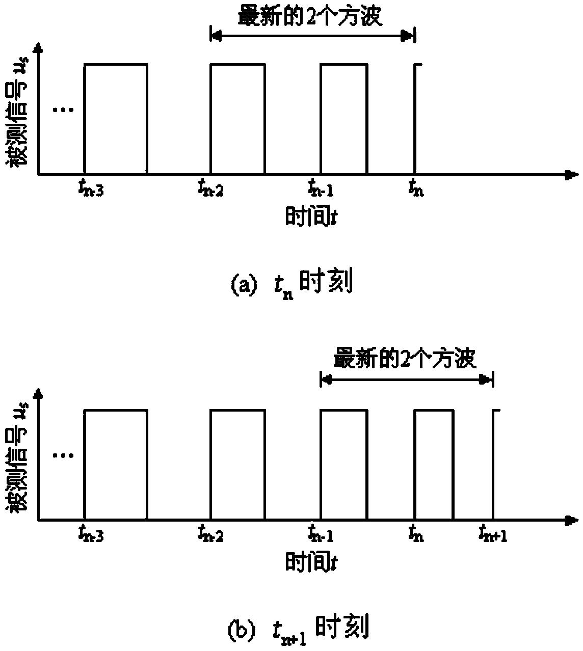
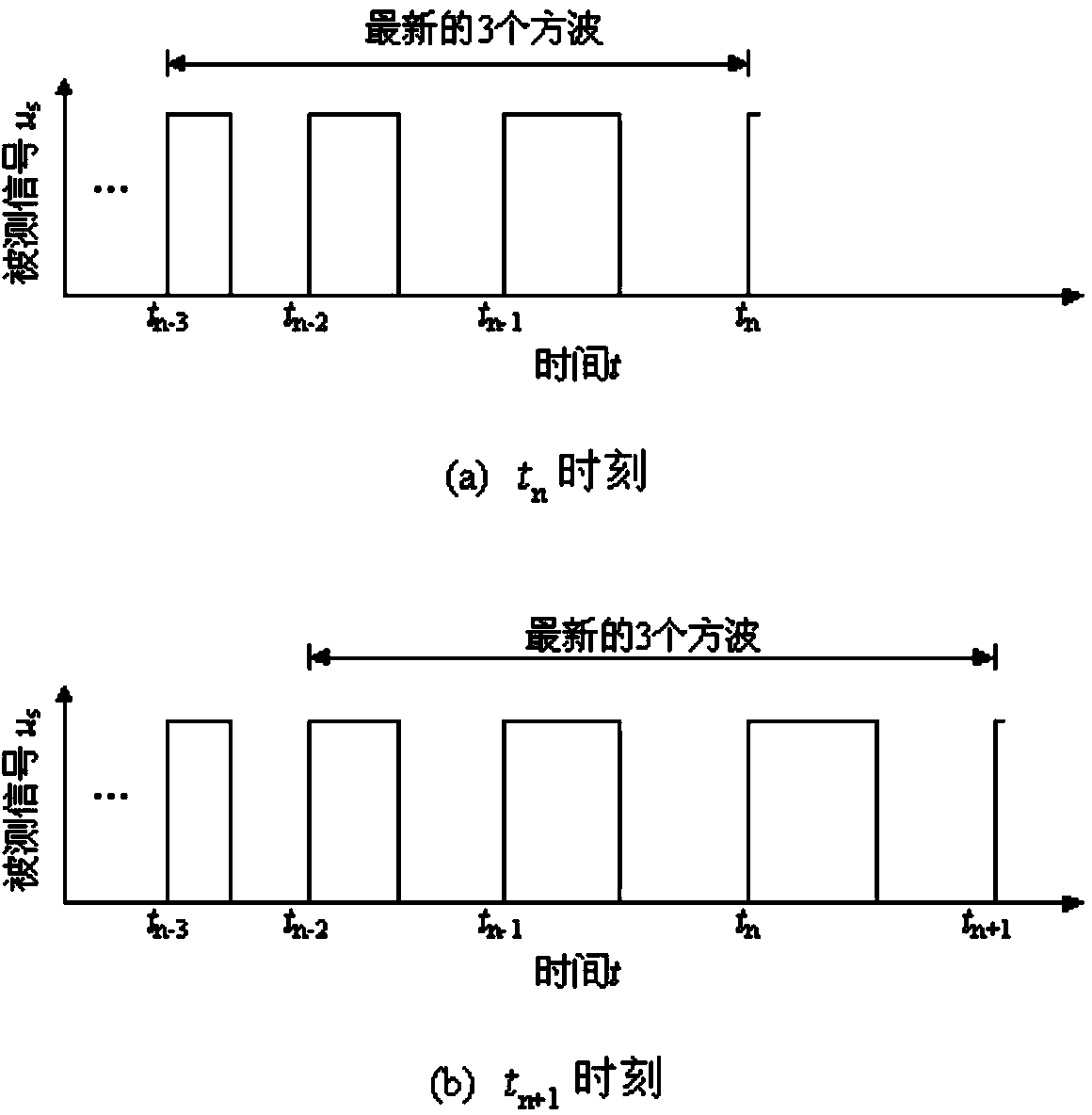
[0044] The linear fitting prediction method is a method of predicting the future frequency based on the time width of the two most recent square waves. Let the linear fitting formula for predicting frequency be

[0045] f(t)=at+b (1)

[0046] In the formula, a and b are coefficients. After solving these two coefficients, the future frequency can be predicted according to this formula.

[0047] Such as figure 1 As shown in (a), take the latest two square waves, and the process of solving a and b is as follows:

[0048] at t n-1 Time, can be calculated [t n-2 , t n-1 ] The average frequency of time period is and as The frequency of time, that is f ( t n - 1 ...


PUM


Abstract

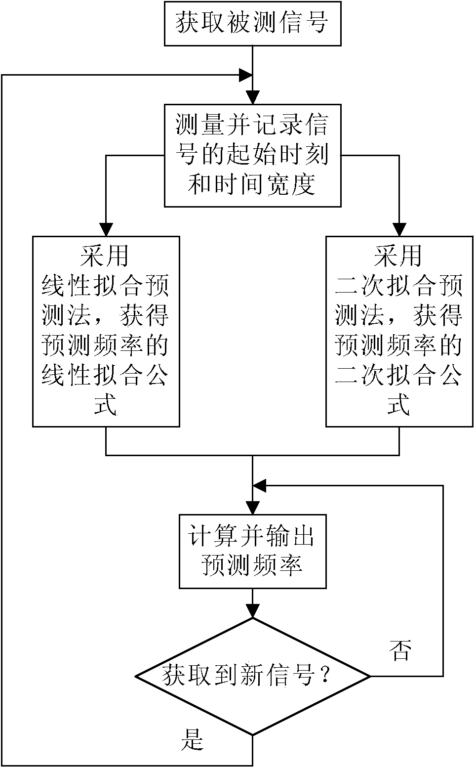
A signal frequency real-time measuring method based on low-frequency square signal frequency prediction comprises the steps that (1) tested square signals are obtained; (2) the initial moment and the time width of the square signals are measured and recorded; (3) a linear fitting prediction method or a quadratic fitting prediction method is used, and a frequency linear fitting formula or a frequency quadratic fitting formula of tested signals is obtained; (4) prediction frequency is computed in real time and output; and (5) whether new signals are obtained is judged, if yes, the step (2) is carried out, and otherwise the step (4) is carried out. Prediction values are used for replacing measuring values to be used as output values, the prediction values can compensate the hysteresis errors existing in the measuring values, accordingly, the accuracy of real-time frequency measuring is improved, the measuring accuracy of steady state frequency is not lowered, an extra timer is not occupied, computing quantity is small, and meanwhile the hardware cost of frequency testing equipment cannot be increased.

Description

technical field [0001] The invention relates to the technical field of signal testing, in particular to a method for real-time measurement of signal frequency. Background technique [0002] In the frequency measurement equipment, the signal is measured by sensor sensing, conditioning circuit shaping, processor acquisition and calculation, etc., because each link takes time, so the measured value lags behind the actual value in time, when the actual frequency is constantly changing When , the measured value will produce a lag error due to the time lag. Current frequency measurement equipment such as frequency testers and tachometers use the measured value as the output value, so there is also a hysteresis error. [0003] The timer clock frequency of the current single-chip microcomputer and data acquisition card is usually tens of MHz. Except for the communication field, in most control systems, the measured signal is a square wave signal with a frequency lower than 100KHz. ...

Claims


Application Information

Patent Timeline
IPC IPC(8): G01R23/02
Inventor 郝允志林毓培周黔
Owner SOUTHWEST UNIVERSITY
Learn More