
Novel bladeless oil smoke exhausting device

An exhaust device and oil fume technology, which is applied to the removal of oil fume, household heating, lighting and heating equipment, etc., can solve the problems of dust and oil deposits on the impeller, and it is difficult to clean, so as to reduce the fouling area, simple structure and simple operation. Effect

Inactive Publication Date: 2014-08-27
昆山洛博格机械技术咨询有限公司
View PDF8 Cites 4 Cited by
  • Summary
  • Abstract
  • Description
  • Claims
  • Application Information

AI Technical Summary

Problems solved by technology

[0005] However, the existing exhaust fans generally have a rotating impeller structure. After a long time, dust or oil stains are deposited on the impeller, which is difficult to clean.

Method used


Image

  • Novel bladeless oil smoke exhausting device

Examples


Embodiment Construction

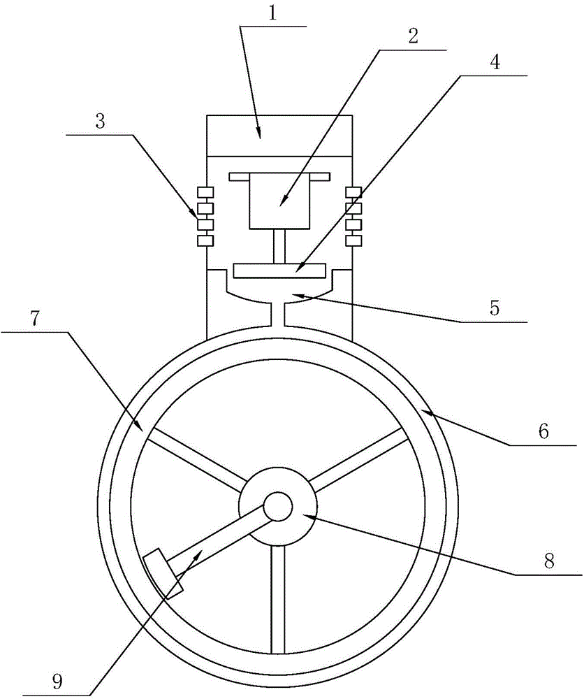
[0011] see figure 1 , this specific embodiment adopts the following technical solutions: it includes oil fume exhaust device 1, first drive motor 2, air intake hole 3, rotating fan blade 4, funnel air pipe inlet nozzle 5, annular guide air path 6, circular Smoke exhaust bracket 7, second drive motor 8, rotary oil suction scraper 9, the inside of the oil fume exhaust device 1 is provided with a first drive motor 2, and several air intake holes 3 are provided on both sides of the first drive motor 2 , the lower end of the first drive motor 2 is provided with a rotating fan blade 4, the lower end of the rotating fan blade 4 is provided with a funnel air pipe inlet nozzle 5, and the lower end of the oil fume exhaust device 1 is provided with an annular guide air passage 6, and the funnel air pipe intake The mouth 5 is connected with the annular flow guide air path 6, and the inside of the ring flow guide air path 6 is provided with a circular smoke exhaust support 7, and the middl...


PUM


Abstract

The invention relates to a novel bladeless oil smoke exhausting device, in particular to the technical field of electrical equipment. A first driving motor is arranged in the oil smoke exhausting device; a plurality of air inlet holes are formed in the two sides of the first driving motor; a rotating blade is arranged at the lower end of the first driving motor; a funnel air pipe air inlet nozzle is arranged at the lower end of the rotating blade; an annular diversion air course is arranged at the lower end of the oil smoke exhausting device; the funnel air pipe air inlet nozzle is connected with the annular diversion air course; a circular smoke discharging bracket is connected to the inside of the annular diversion air course; and a second driving motor is arranged in the middle of the circular smoke discharging bracket, and is connected with a rotary oil absorption scraper. The novel bladeless oil smoke exhausting device has a simple structure, changes the structure of a traditional impeller exhaust fan, and reduces the scaling area; and meanwhile, as the rotary oil absorption scraper is arranged, the novel bladeless oil smoke exhausting device can automatically clean dust on the circular smoke discharging bracket so as to achieve the effects of convenience and practicability.

Description

Technical field: [0001] The invention relates to the technical field of electrical equipment, in particular to a novel leafless oil fume exhaust device. Background technique: [0002] Exhaust fan, a type of air-conditioning appliance that is driven by a motor to rotate the fan blades to drive airflow to exchange indoor and outdoor air. Also known as ventilation fan. The purpose of exhaust is to remove indoor dirty air, adjust temperature, humidity and sensory effects. Exhaust fans are widely used in homes and public places. [0003] Exhaust fans are also called negative pressure fans, negative pressure fans, etc. Exhaust fans use air convection to keep the room in a negative pressure state, forming a suction force, continuously inhaling outdoor air, and exhausting indoor stuffy air, so as to achieve the effect of ventilation and cooling. [0004] The exhaust fan has the characteristics of low investment cost, large air volume, low noise, low energy consumption, stable op...

Claims


Application Information

Patent Timeline
Patent Type & Authority Applications(China)
IPC IPC(8): F24C15/20
Inventor 沈亮亮
Owner 昆山洛博格机械技术咨询有限公司
Learn More