In vitro regeneration countercurrent ion exchange system and method of use

An ion exchange and in vitro regeneration technology, applied in ion exchange, ion exchange regeneration, ion exchange water/sewage treatment and other directions, can solve the problems of low water saving rate, inability to continuously produce water, high consumption of regeneration liquid, and achieve energy saving and time, to ensure the quality of continuous water production, the effect of stable water quality

Active Publication Date: 2015-12-02
CHENGDU GRACE FIBER +1
View PDF2 Cites 0 Cited by
  • Summary
  • Abstract
  • Description
  • Claims
  • Application Information

AI Technical Summary

Problems solved by technology

However, there are still the following disadvantages: continuous water production is not possible, and multiple units need to be invested to exchange water production, the water saving rate is still low, and the consumption of regeneration fluid is high

Method used


Image

  • In vitro regeneration countercurrent ion exchange system and method of use

Examples


Embodiment 1

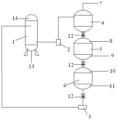
[0032] The in vitro regenerative countercurrent ion exchange system includes an ion exchanger, an ejector, a collection tank, a regeneration tank, and a cleaning tank; the ion exchanger, ejector, collection tank, regeneration tank, and cleaning tank are connected in sequence, and the collection tank The bottom is connected to the top of the regeneration tank, the bottom of the regeneration tank is connected to the top of the cleaning tank, the bottom of the cleaning tank is connected back to the ion exchanger, and an injector is arranged between the cleaning tank and the ion exchanger; the collecting tank The upper part is provided with a water outlet, the lower part of the regeneration tank is provided with a liquid inlet, and the upper part is provided with a liquid discharge port, the lower part of the cleaning tank is provided with a water inlet, and the upper part is provided with a drain port.

Embodiment 2

[0034] This embodiment is basically the same as Embodiment 1, on this basis:

[0035] The water inlet of the ion exchanger is at the bottom of the exchanger, and the water outlet is at the upper part of the exchanger.

[0036] The ion exchanger is provided with two sampling points, one at the tank outlet and one at the 2 / 3 of the tank. The user needs the indicator to be tested at the tank outlet, and the 2 / 3 test indicator of the tank is the set indicator. When the hardness is just lower than the user's indicator, increase the flow rate of the recycled resin (control the flow rate of the injector) or reduce the flow rate of the raw water.

Embodiment 3

[0038] This embodiment is basically the same as Embodiment 1, on this basis:

[0039] The water inlet of the ion exchanger is at the bottom of the exchanger, and the water outlet is at the upper part of the exchanger.

[0040] The water outlet of the collection tank is connected to the liquid storage container, and the liquid storage container is connected to the water inlet of the cleaning tank.


PUM


Abstract

The invention provides an external regeneration reverse-flow ion exchange system and an application method of the external regeneration reverse-flow ion exchange system. The external regeneration reverse-flow ion exchange system comprises an ion exchanger, an ejector, a collecting tank, a regeneration tank and a cleaning tank, wherein the ion exchanger, the ejector, the collecting tank, the regeneration tank and the cleaning tank are connected in sequence, the bottom of the collecting tank is connected with the top of the regeneration tank, the bottom of the regeneration tank is connected with the top of the cleaning tank, the bottom of the cleaning tank is connected back to the ion exchanger, the ejector is arranged between the cleaning tank and the ion exchanger, a water outlet is formed in the collecting tank, a liquid inlet is formed in the lower portion of the regeneration tank, a liquid discharge outlet is formed in the upper portion of the regeneration tank, a water inlet is formed in the lower portion of the cleaning tank, and a water discharging outlet is formed in the upper portion of the cleaning tank. According to the application method of the external regeneration reverse-flow ion exchange system, ion exchange resin out of work is processed through reverse flow regeneration outside the exchanger and then returns to the exchanger, soft water can be continuously produced, energy consumption is reduced, and the equipment utilization rate is increased.

Description

technical field [0001] The invention belongs to the field of soft water industrial water, and in particular relates to an in vitro regeneration countercurrent ion exchange system and a use method thereof. Background technique [0002] In the water treatment of the prior art, a sodium ion exchange resin of a certain height is generally installed in the sodium ion exchanger as an exchange agent. The raw water passes through the exchanger (downstream or countercurrent), and the sodium ions on the exchanger replace the calcium and magnesium ions in the raw water, softening the water. [0003] Ca 2+ +2NaR→CaR+2Na + [0004] Mg 2+ +2NaR→MgR+2Na + [0005] The sodium ions on the exchanger are gradually replaced by calcium and magnesium ions. After a period of use, calcium and magnesium ions will leak out. When the hardness of the water reaches the specified value, it will stop running and start regeneration. During regeneration, 5-8% brine is passed through the exchange medi...

Claims


Application Information

Patent Timeline
Patent Type & Authority Patents(China)
IPC IPC(8): B01J49/00C02F1/42B01J49/75
Inventor 冷衍辉况波
Owner CHENGDU GRACE FIBER
Why Eureka
Try Eureka