
Spray guns for desulfurization and denitrification

A technology of desulfurization, denitrification, and spray gun, which is applied in the direction of spraying device, liquid spraying device, gas treatment, etc. It can solve the problems that affect the safety of equipment operators, the fluid cannot be sprayed with granularity, and the mixing effect cannot be achieved, so as to reduce the operating requirements. , Simplify the trouble of control, improve the effect of work efficiency

Inactive Publication Date: 2016-06-22
姜建勇
View PDF7 Cites 0 Cited by
  • Summary
  • Abstract
  • Description
  • Claims
  • Application Information

AI Technical Summary

Problems solved by technology

[0004] At present, in desulfurization and denitrification, flue gas conditioning and other processes, it is necessary to spray the fluid to a certain position with a spray gun to achieve an ideal mixing effect; when in use, the spray gun is in high-temperature flue gas, and over time, the high-temperature flue gas will make the The spray gun and the fluid in the barrel are overheated, and the fluid tends to vaporize in the barrel, causing the pressure in the spray gun to rise. Due to the change in the pressure in the barrel, the fluid cannot be sprayed to a certain position with the expected particle size, which is not ideal. The blending effect of
[0005] In addition, the increase in the internal pressure of the strong pipe caused by fluid gasification can lead to the bursting of the spray gun in severe cases, and the service life is short, which affects the safety of equipment and operators. The above problems have been technical problems for many years and urgently need to be solved.

Method used


Image

  • Spray guns for desulfurization and denitrification
  • Spray guns for desulfurization and denitrification

Examples


Embodiment Construction

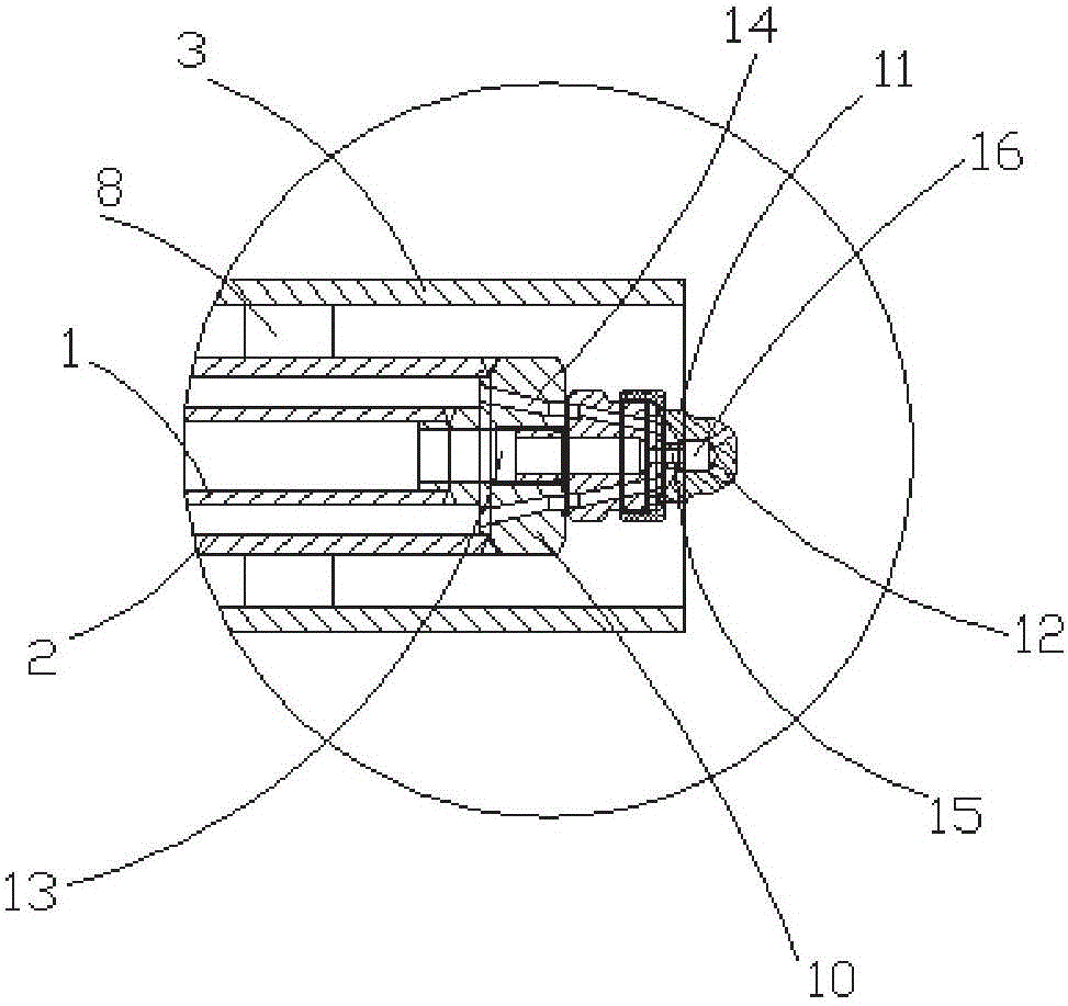
[0021] like figure 1 and figure 2 As shown, the present invention relates to a spray gun for desulfurization and denitrification, which is characterized in that: it includes an inner tube 1, a middle tube 2 and an outer tube 3 arranged sequentially from the inside to the outside, and one end of the middle tube 2 is connected to the inner tube 3. The outer wall of the tube 1 forms a sealed and fixed connection, and the other end and one end of the inner tube 1 jointly form a nozzle assembly, and the outer wall of the middle tube 2 is provided with a movable flange 4 and an air intake pipe 5; the outer wall of the outer tube 3 There is a fixed flange 6 matched with the movable flange 4 on the top, a connection pipe 7 is provided on the outer wall of the outer tube 6 , and support blocks 8 distributed around the circumference are formed between the inner wall and the middle tube 2 .

[0022] In order to improve the spraying effect, the nozzle assembly in the present invention i...


PUM


Abstract

The invention discloses a spray gun for desulfurization and denitrification. The spray gun comprises an inner pipe, a middle pipe and an outer pipe, wherein the inner pipe, the middle pipe and the outer pipe are sequentially arranged from inside to outside. One end of the middle pipe is fixedly connected with the outer wall of the inner pipe in a sealed mode, and the other end of the middle pipe and one end of the inner pipe commonly form a nozzle assembly. The outer wall of the middle pipe is provided with a movable flange and a gas inlet pipe. The outer wall of the outer pipe is provided with a fixed flange matched with the movable flange. The outer wall of the outer pipe is provided with a connecting pipe, and supporting blocks which are distributed circumferentially are formed between the inner wall of the outer pipe and the middle pipe. The nozzle assembly comprises a nozzle seat, a conical nozzle is arranged on the nozzle seat, and six to eight spray holes which are circumferentially distributed are formed in the end of the nozzle. The spray gun for desulfurization and denitrification improves the desulfurization and denitrification working efficiency, prolongs the service life and reduces using cost for an enterprise.

Description

technical field [0001] The invention relates to a spray gun for desulfurization and denitrification. Background technique [0002] The desulfurization and denitrification tower is mainly composed of a flue gas conveying system, an absorption tower, a spray system, a slurry circulation system, and a slurry recovery system. [0003] The industrial waste gas transports a large amount of sulfur dioxide, carbon dioxide, etc. waste gas to the absorption tower through the flue gas conveying system. A large amount of desulfurization agent in the absorption tower is transported to the tower body by the spray system. The desulfurizer and industrial waste gas with a certain pressure and detachment ability Full contact produces a chemical reaction. In order to make the sulfur dioxide in the waste gas form a precipitate and flow to the bottom of the tower, it is discharged from the slurry circulation system to the outside of the tower for recycling. After desulfurization and purification...

Claims


Application Information

Patent Timeline
Patent Type & Authority Patents(China)
IPC IPC(8): B05B7/04B01D53/78B01D53/60
CPCB01D53/60B01D53/78B01D2257/302B01D2257/40B01D2259/124B05B7/045
Inventor 姜建勇
Owner 姜建勇
Learn More