
Flywheel hybrid system

A kinetic energy recovery system and clutch technology, applied in hybrid vehicles, mechanical hybrid vehicles, machines/engines, etc., can solve problems such as frequency reduction and generator speed reduction

Inactive Publication Date: 2014-08-20
THE GATES CORP
View PDF9 Cites 4 Cited by
  • Summary
  • Abstract
  • Description
  • Claims
  • Application Information

AI Technical Summary

Problems solved by technology

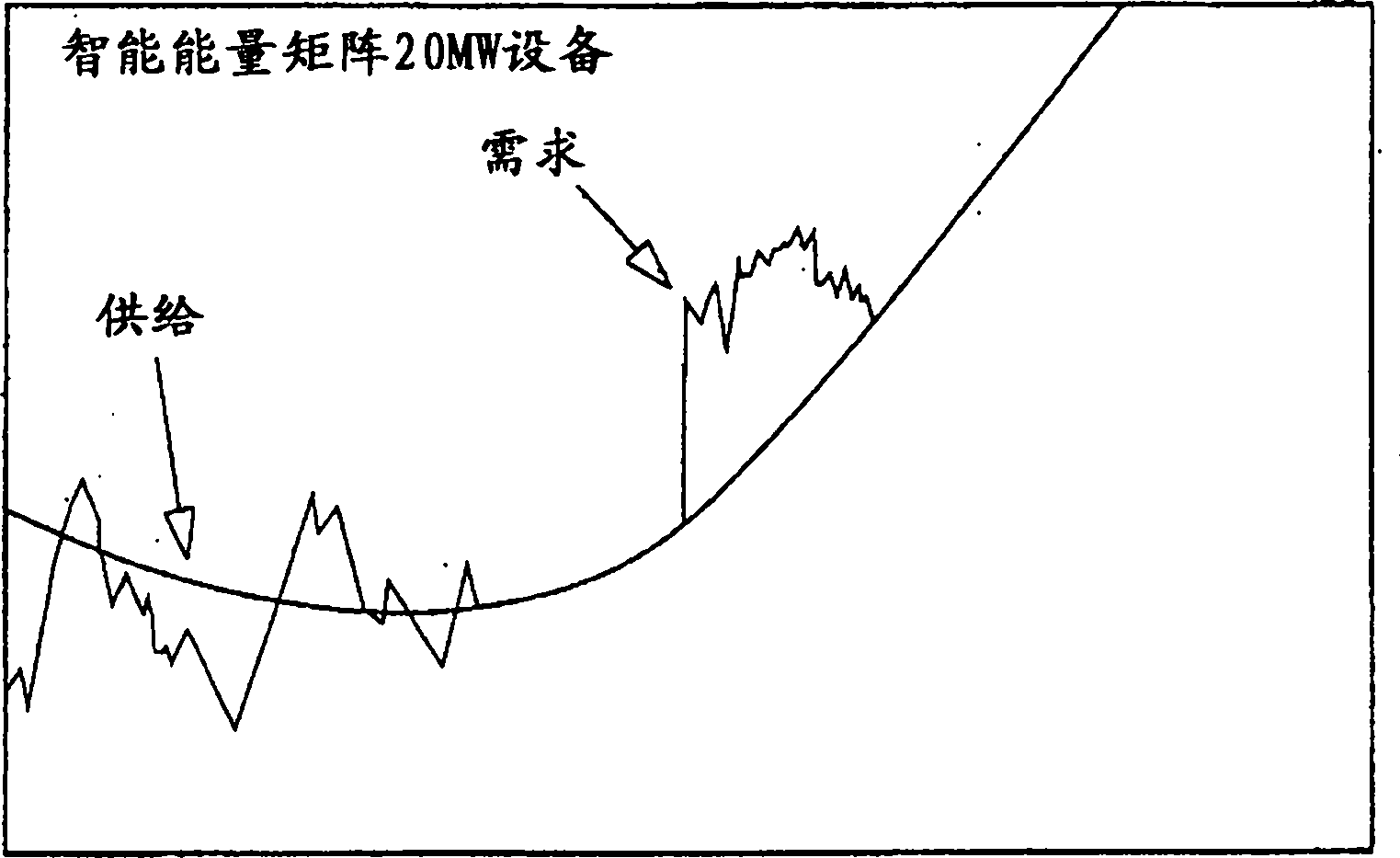
As shown in Figure 1A, when the required power is high, the generator speed decreases, causing a decrease in the frequency of the supplied AC power

Method used


Image

  • Flywheel hybrid system
  • Flywheel hybrid system
  • Flywheel hybrid system

Examples


Embodiment Construction

[0028] The following description provides examples only, and is not intended to limit the scope, application, or structure of the claims. Rather, the following description merely provides those skilled in the art with exemplary descriptions for implementing the same. It being understood that various changes may be made in the function and arrangement of elements without departing from the spirit and scope of the appended claims.

[0029] The inventive system includes a kinetic energy recovery system (KERS) for driving an internal combustion engine belt drive auxiliary system (ABDS). The dual-clutch configuration allows either the internal combustion engine or the flywheel to drive the accessories.

[0030] Significant fuel savings can be achieved if energy that would otherwise be wasted when the vehicle brakes are applied is recovered and stored for later use for propelling accessories. Typically, regenerative braking energy is used to propel the vehicle, which is not effici...


PUM


Abstract

A kinetic energy recovery system for a belt driven accessory system comprising a kinetic energy storage device, a driver having a driver output, a transmission having a gear ratio connected to the driver output, a belt driven accessory system connected to the transmission through a first clutch, the kinetic energy storage device connected to the belt driven accessory system through a second clutch, and the kinetic energy storage device and the transmission connectable through the first clutch and second clutch.

Description

technical field [0001] The present invention relates to a flywheel hybrid system, and more particularly to a flywheel hybrid system including a flywheel selectively connected to an internal combustion engine accessory belt drive system. Background technique [0002] A flywheel is a well known device for storing energy and regulating speed. On vehicles, including automobiles, a large flywheel is typically mounted to the crankshaft. The flywheel inertia serves to smooth out the impulsive nature of the internal combustion process and prevent speed fluctuations from being transmitted to the transmission and other components of the drivetrain. [0003] Other uses for flywheels are also known. For example, flywheels are used to regulate grid frequency. As shown in FIG. 1A , as shown in FIG. 1 , when the required power is high, the generator speed decreases, causing a decrease in the frequency of the supplied AC power. During peak demand, the flywheel system can provide power, ...

Claims


Application Information

Patent Timeline
IPC IPC(8): F02B67/06B60K6/10B60K25/00B60L50/30
CPCY10T74/19865Y02T10/6204B60K6/105Y02T10/6282B60K2025/005B60K25/02F02B67/06Y02T10/62Y02T10/70
Inventor A·塞基I·阿里
Owner THE GATES CORP
Learn More