
Crown for an aircraft tire

A technology for tires and crown reinforcements, which is applied to the reinforcement layer of pneumatic tires, aircraft tires, tire parts, etc., and can solve problems that are not conducive to aircraft payloads

Inactive Publication Date: 2014-08-20
MICHELIN & CO (CIE GEN DES ESTAB MICHELIN)
View PDF7 Cites 3 Cited by
  • Summary
  • Abstract
  • Description
  • Claims
  • Application Information

AI Technical Summary

Problems solved by technology

[0008] The aforementioned protective or fragmentation devices have the disadvantage of constituting an additional structural element, the additional mass of which is detrimental to the payload of the aircraft

Method used


Image

  • Crown for an aircraft tire
  • Crown for an aircraft tire
  • Crown for an aircraft tire

Examples


Embodiment Construction

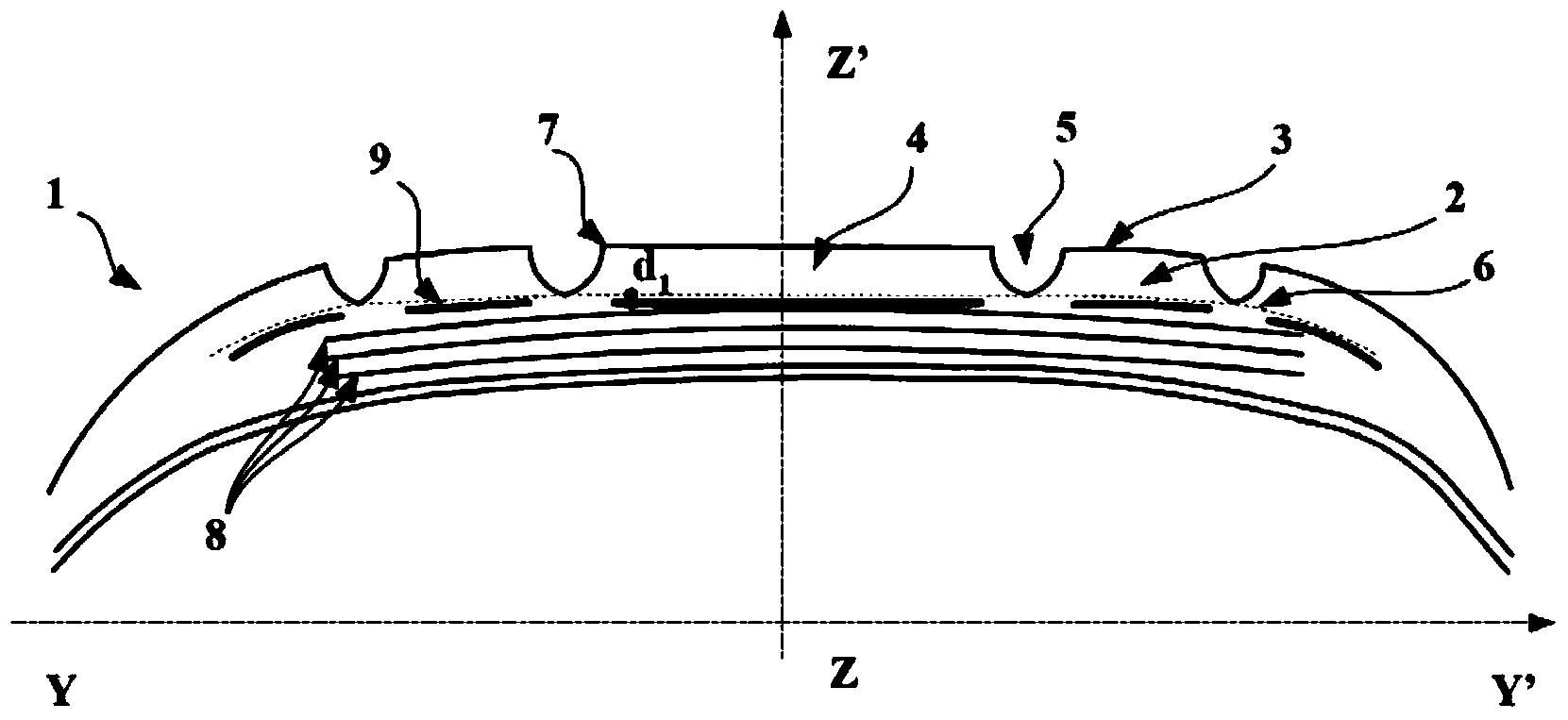
[0056] figure 1 A meridian section through the crown of the tire 1 is shown, ie a section in the meridian plane (YY', ZZ'), where the directions YY' and ZZ' are the axial and radial directions respectively. The direction XX' (not shown) is the circumferential direction. The plane (XX', ZZ') is the equatorial plane.

[0057] figure 1 A tire 1 for aircraft is shown comprising a tread 2 intended to come into contact with the ground via a tread surface 3 arranged radially between an underside 6 and the tread surface 3 . The tread 2 comprises at least 5 circumferential ribs 4 which, in this case, are adjacent to at least one circumferential groove 5 . Each circumferential rib 4 extends radially between the bottom surface 6 and the tread surface 3 and extends axially in the tread surface 3 between two edge corners 7 . the axially outermost shoulder circumferential rib is bounded axially on the inside by the edge corner and on the outside by the axial limit of the ground-contac...


PUM


Abstract

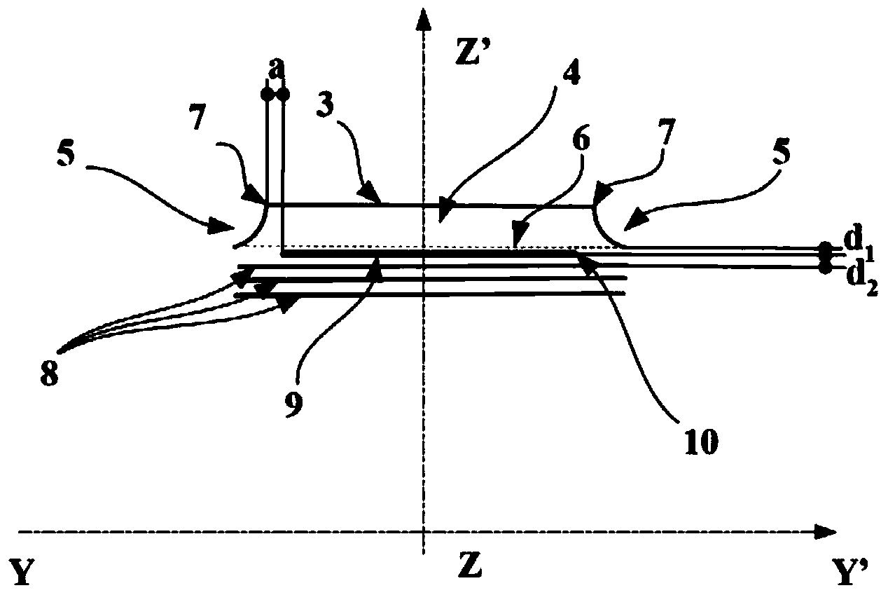
The present invention relates to a tire for an aircraft and in particular to the crown of a tire for an aircraft, and the aim of the invention is to decrease the size and thus the weight of the pieces of the tread, in the event of an accidental separation thereof from the tire, without using additional devices that are external to the tire, and thus without reducing the payload of the aircraft. An aircraft tire (1) includes a tread (2) which is to contact the ground via a rolling surface (3) and which is radially arranged between a bottom surface (6) and the rolling surface (3), the tread (2) including at least two circumferential ribs (4) adjacent to at least one circumferential groove (5), each circumferential rib (4) extending radially between the bottom surface (6) and the rolling surface (3) and axially between two ridges (7) in the rolling surface (3), and a crown reinforcement (8) which is radially interior to the bottom surface (6). According to the invention, a separation layer (9) is arranged radially inside at least one circumferential rib (4) between the bottom surface (6) and the crown reinforcement (8), axially between the two ridges (7) of said circumferential rib (4), in the rolling surface (3), and circumferentially over at least a portion of the circumference of the tire (1), and the radial distance (d1) between the separation layer (9) and the bottom surface (6) is equal to at most 1 mm.

Description

technical field [0001] The present invention relates to a tire for aircraft, in particular to the crown of an aircraft tire. Background technique [0002] Aircraft manufacturers are constantly concerned with passenger safety and therefore with reducing the risk of sabotage of their aircraft. Considering the failure modes, partial or complete loss of the tread of a tire equipped with an aircraft landing gear is a critical failure mode that occurs during the take-off or landing phase of an aircraft. [0003] Said mode of failure occurs in particular when the tire runs over blunt objects that may happen to be present on the runway. Taking into account the severe conditions of use of aircraft tires, characterized by high inflation pressures and high static loads and high speeds, the tread of the tire running over blunt objects causes damage to the tread, which often results in cutting of the tread, And subsequently lead to the ejection of tread fragments of different geometric...

Claims


Application Information

Patent Timeline
Patent Type & Authority Applications(China)
IPC IPC(8): B60C19/00B60C9/18
CPCB60C2009/2019B60C2200/02B60C9/20B60C9/0042B60C9/18B60C9/2003B60C2009/2041B60C2009/2016
Inventor F·尚布里亚G·罗什
Owner MICHELIN & CO (CIE GEN DES ESTAB MICHELIN)
Learn More