System for remotely controlling power supply of camera

A power control and camera technology, applied in CCTV systems, components of TV systems, TVs, etc., can solve the problems of inconvenient processing methods and long processing time, so as to increase effective running time, reduce workload, and shorten troubleshooting. effect of time

Inactive Publication Date: 2014-08-20
STATE GRID CORP OF CHINA +1
View PDF5 Cites 3 Cited by
  • Summary
  • Abstract
  • Description
  • Claims
  • Application Information

AI Technical Summary

Problems solved by technology

[0003] The purpose of the present invention is to solve the problems of long processing time and inconvenient processing methods for camera crashes at present, and provide a remote power control system for cameras that shortens the fault processing time, reduces the workload of maintenance personnel, and improves maintenance efficiency

Method used


Image

  • System for remotely controlling power supply of camera

Examples


Embodiment

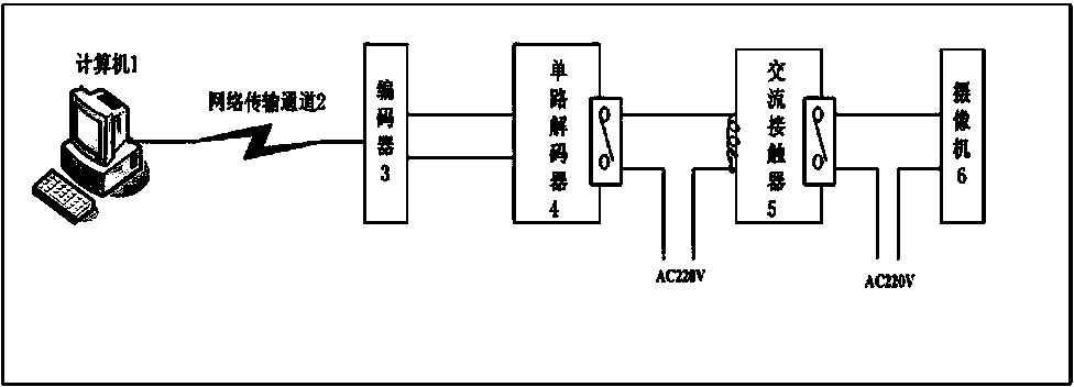
[0013] When the maintenance personnel find that a certain camera has a crash, the maintenance personnel log in to the camera control program in the computer 1, control the virtual camera light control switch corresponding to the camera 6, turn on the light switch, and the turn-on signal is transmitted to the encoder through the network transmission channel 2 3. Encoder 3 converts the opening signal to 485 signal and transmits it to single-channel decoder 4. Single-channel decoder 4 output switch is switched from closed to open, the coil of AC contactor 5 is de-energized, and the switch is also switched from closed to open. The camera 6 is powered off, and then the maintenance personnel turn off the virtual camera light control switch, the shutdown signal is transmitted to the encoder 3 through the network transmission channel 2, and the encoder 3 converts the shutdown signal to a 485 signal and transmits it to the single-channel decoder 4, single-channel decoding The output swit...


PUM


Abstract

A system for remotely controlling a power supply of a camera comprises a computer with a camera control program, a network transmission channel, an encoder, a one-way decoder, an alternating current contactor and the camera. The computer is connected to the encoder through the network channel, a 485 signal output port of the encoder is connected to a signal input port of the one-way decoder, an output switch of the one-way decoder and an induction coil of the alternating current contactor are connected in series to form a loop, and an output switch of the alternating current contactor and the input end of the power supply of the camera are connected in series to form a loop. According to the system, through the virtual camera, the switch of the one-way decoder is controlled by controlling lamplight control signals of the virtual camera, a normally-closed switch of the alternating current contactor is controlled, and then the goal of controlling the power supply of the camera is achieved. Common faults of the camera can be rapidly processed, and fault time is shortened; meanwhile, labor force can be greatly saved and the camera is convenient to manage.

Description

Technical field [0001] The invention relates to a remote power control system of a camera, which belongs to the technical field of electrical equipment. Background technique [0002] The video surveillance system has very important practical significance for ensuring the safe and normal working environment of the power system. Most of the cameras in the video surveillance system of the power system run outdoors. Due to the large changes in outdoor temperature and humidity, the complex wind and sun environment, and frequent camera failures, statistics show that 80% of camera failures are crash failures. You can restart the camera power supply To restore to normal, and restarting the power requires maintenance personnel to rush to the scene to perform operations, which greatly extends the troubleshooting time, and the camera failure is not divided into time periods, and often needs to be repaired during the maintenance period, which also greatly increases the maintenance The workl...

Claims


Application Information

Patent Timeline
Patent Type & Authority Applications(China)
IPC IPC(8): H04N5/232H04N7/18
Inventor 项敏张群江大卫丁元东严安曹准福徐伟平项宏伟
Owner STATE GRID CORP OF CHINA
Why Eureka
Try Eureka