Water flow splitting device

A diverting device and water flow technology, applied in fluid heaters, lighting and heating equipment, etc., can solve the problems of large disturbance, decreased energy efficiency ratio, increased mixing of cold and hot water, etc., to reduce the impact of water flow, rational distribution and The effect of diversion and low mixing degree of cold and hot water

Inactive Publication Date: 2014-08-20
广西申能达智能技术有限公司
View PDF7 Cites 2 Cited by
  • Summary
  • Abstract
  • Description
  • Claims
  • Application Information

AI Technical Summary

Problems solved by technology

[0003] (1) The directionality of the water flow is not clear enough and the distribution of the water flow is not uniform enough, and the disturbance is large, which increases the mixing of cold and hot water, which affects the effect of water temperature stratification, resulting in insufficient water temperature stratification, and the increase of the inclined temperature layer of cold and hot water separation. Large, affecting the energy efficiency ratio of heat pump heating
[0004] (2) Water flow diversion device without flow adjustment
[0005] In recent years, there have also been devices that can divide and stratify the water flow, such as the Chinese patent application number 201020676762.0, an intelligent control heating cabinet heat pump water supply system with a built-in water temperature stratified water flow device, involving a 4H-shaped water temperature stratified water flow device ,The 4H-shaped water flow device cannot completely cover the entire hot water tank, and the water is only buffered once when entering the water tank and the water is only discharged through two rows of holes. decline

Method used


Image

  • Water flow splitting device
  • Water flow splitting device
  • Water flow splitting device

Examples


Embodiment Construction

[0031] The specific embodiments of the present invention will be described in detail below in conjunction with the accompanying drawings, but it should be understood that the protection scope of the present invention is not limited by the specific embodiments.

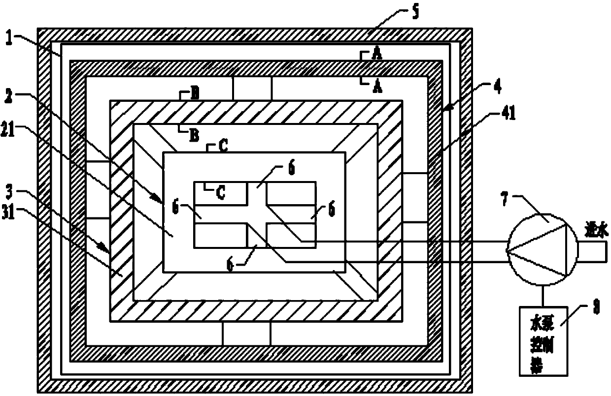
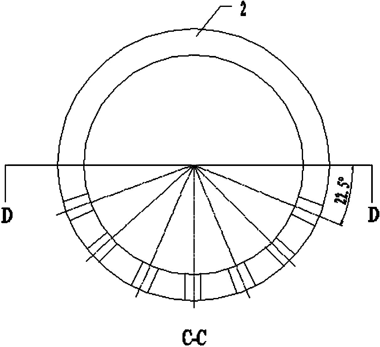
[0032] Such as Figure 1-2 The shown water distribution device 1 includes an internal water distributor 2, a middle water distributor 3, and an external water distributor 4; the internal water distributor 2 is a first rectangular frame surrounded by a first pipeline 21, and the first pipeline 21 is provided with 7 rows of small holes arranged in dislocations (such as image 3 with Image 6 As shown), the aperture of the small hole is preferably 0.5-1mm, and a water inlet 6 is provided in the middle of the four sides in the first rectangular frame. The middle water distributor 3 is a second rectangular frame surrounded by the second pipe 31, the second rectangular frame is arranged around the periphery of the first re...


PUM


Abstract

The invention discloses a water flow splitting device which is mounted in a hot water tank. The water flow splitting device comprises water flow splitting device bodies. Each water flow splitting device body comprises an internal water distributor, a middle water distributor and an external water distributor, wherein the middle water distributor surrounds the periphery of the internal water distributor and is communicated with the internal water distributor, and the external water distributor surrounds the periphery of the middle water distributor and is communicated with the middle water distributor. The internal water distributor, the middle water distributor and the external water distributor are respectively provided with five to seven rows of small holes, the internal water distributor is provided with a water inlet. The water flow splitting device bodies are arranged on the upper portion and the lower portion in the hot water tank respectively, the small holes of the water flow splitting device body mounted on the upper portion in the hot water tank face downwards, and the small holes of the water flow splitting device body mounted on the lower portion in the hot water tank face upwards. The water flow splitting device can reduce impact force generated when water flows into the water tank and greatly improves the layering effect and the energy efficiency ratio.

Description

technical field [0001] The invention relates to the field of water flow diversion, in particular to a water flow diversion device. Background technique [0002] The heat pump industry is an industry with relatively high technical content. How to solve the stability, adaptability and intelligence of heat pump operation is the key point that heat pump enterprises urgently need to solve. In order to improve the heating efficiency of the heat pump system, a water flow diversion device is added to the water tank, so that the incoming and outgoing water can be introduced and exported smoothly, and the hot and cold water are less disturbed and not mixed with each other during the heating process, thus ensuring the high energy efficiency of the heat pump operation. Compare. However, there are two major problems with the water flow diversion device in the current heat pump system: [0003] (1) The directionality of the water flow is not clear enough and the distribution of the wate...

Claims


Application Information

Patent Timeline
Patent Type & Authority Applications(China)
IPC IPC(8): F24H9/00
Inventor 杨华杨宗光李莎
Owner 广西申能达智能技术有限公司
Why Eureka
Try Eureka