


Quick Research
Generate reliable direction feasibility study reports for your R&D in just a few steps.

Technical Q&A
Discover and master advanced knowledge NOW. Basics, ideas, possibilities, all at once.

Find Solutions
As an expert in R&D theories, this can generate solutions to your technical problems instantly.

Evaluate Feasibility
Analyze your overall solution with one click, know your potential R&D risks in advance.

Monitor Landscape
Get weekly tech updates, stay abreast of the latest tech innovations and key insights.
High-pressure-resistant integrated leakage-free rotating compensator
A rotary compensator and no-leakage technology, which is applied in expansion compensation devices for pipelines, sleeve/socket connections, pipes/pipe joints/pipe fittings, etc. Hidden dangers and other problems, to achieve the effect of solving the difficulty of weld flaw detection, improving sealing, and reducing loss
- Summary
- Abstract
- Description
- Claims
- Application Information
AI Technical Summary
Problems solved by technology
Method used
Image

Examples
Embodiment 1
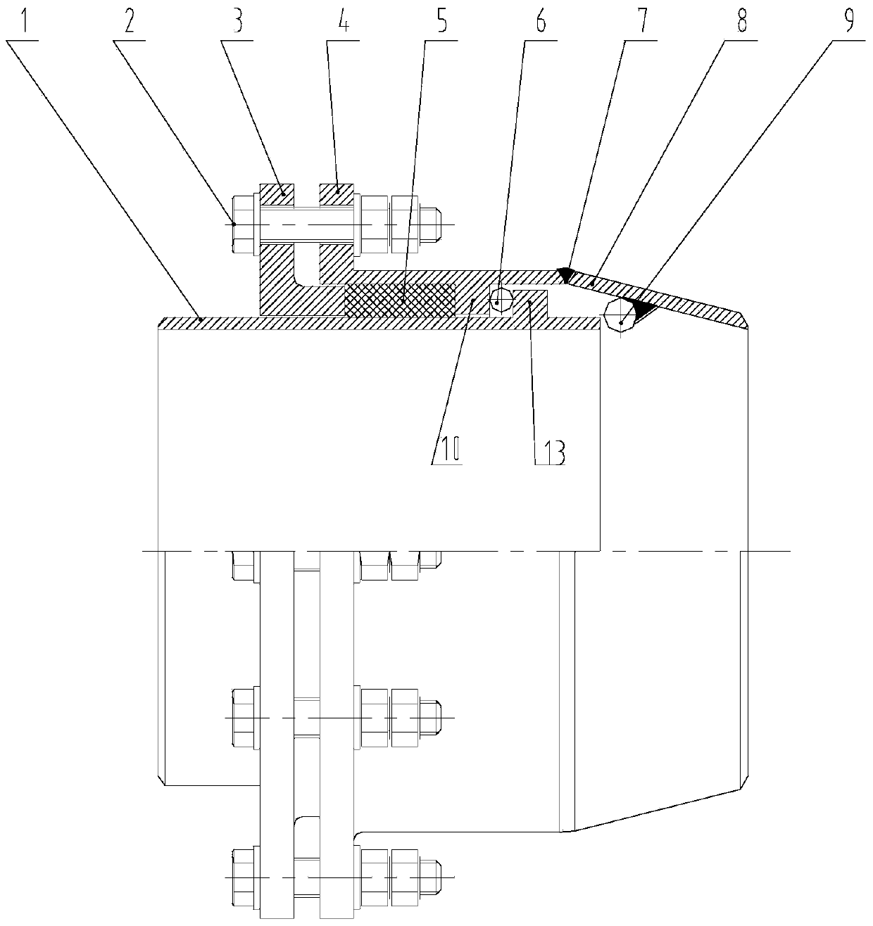
[0031] Such as figure 2 As shown, the high-pressure resistant integrated non-leakage rotary compensator described in this embodiment includes an inner tube 1, an outer tube 4, a connecting tube 8, and a packing flange 3. The outer tube 4 is set on the inner tube 1, and one end of the inner tube 1 Pass through the outer sleeve 4 and insert into the connecting pipe 8 , the connecting pipe 8 is a reducing pipe, and is an integrated structure integrally formed with the outer sleeve 4 . The packing flange 3 is set on the inner tube 1, and one end thereof extends into the outer casing 4, and the inner surface of the outer casing 4 is provided with an annular inner boss 10, and the annular inner boss 10 and the packing flange 3 extend into the outer casing A sealing packing 5 is arranged between one end of the pipe, and an anti-impact plate 14 is arranged between the sealing packing 5 and the annular inner boss 10 on the inner surface of the outer casing, and between the sealing pac...
Embodiment 2
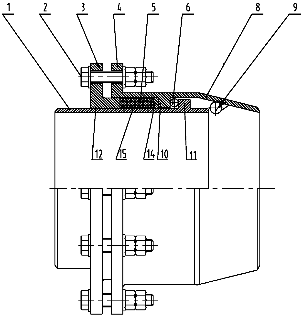
[0037] Such as image 3 As shown, the high-pressure resistant integrated non-leakage rotary compensator described in this embodiment includes an inner tube 1, an outer tube 4, a connecting tube 8, and a packing flange 3. The outer tube 4 is set on the inner tube 1, and one end of the inner tube 1 Pass through the outer sleeve 4 and insert into the connecting pipe 8 , the connecting pipe 8 is a reducing pipe, and is an integrated structure integrally formed with the outer sleeve 4 . The packing flange 3 is set on the inner tube 1, and one end thereof extends into the outer casing 4, and the inner surface of the outer casing 4 is provided with an annular inner boss 10, and the annular inner boss 10 and the packing flange 3 extend into the outer casing A sealing packing 5 is arranged between one end of the pipe, and an anti-impact plate 14 is provided between the sealing packing 5 and the annular inner boss 10 on the inner surface of the outer casing, and between the sealing pack...
Embodiment 3
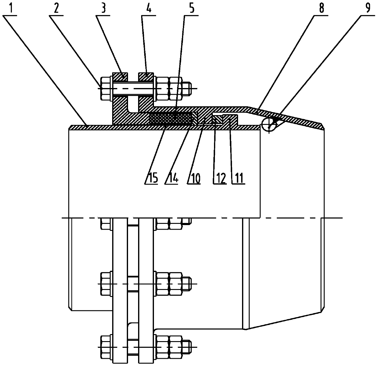
[0042] Such as Figure 4 As shown, the high-pressure resistant integrated non-leakage rotary compensator described in this embodiment includes an inner tube 1, an outer tube 4, a connecting tube 8, and a packing flange 3. The outer tube 4 is set on the inner tube 1, and one end of the inner tube 1 Pass through the outer sleeve 4 and insert into the connecting pipe 8 , the connecting pipe 8 is a reducing pipe, and is an integrated structure integrally formed with the outer sleeve 4 . The packing flange 3 is set on the inner tube 1, and one end thereof extends into the outer casing 4, and the inner surface of the outer casing 4 is provided with an annular inner boss 10, and the annular inner boss 10 and the packing flange 3 extend into the outer casing A sealing packing 5 is arranged between one end of the pipe, and an anti-impact plate 14 is arranged between the sealing packing 5 and the annular inner boss 10 on the inner surface of the outer casing, and between the sealing pac...
PUM
 Abstract
Description
Claims
Application Information
 - R&D Engineer
- R&D Manager
- IP Professional
- Industry Leading Data Capabilities
- Powerful AI technology
- Patent DNA Extraction
Browse by: Latest US Patents, China's latest patents, Technical Efficacy Thesaurus, Application Domain, Technology Topic, Popular Technical Reports.
© 2024 PatSnap. All rights reserved.Legal|Privacy policy|Modern Slavery Act Transparency Statement|Sitemap|About US| Contact US: help@patsnap.com