
Conical rotary flapping wing aircraft

A flapping-wing aircraft and conical technology, applied in the field of aircraft, can solve the problems of difficult vertical lift, high requirements on the fatigue strength of flapping-wing materials, low efficiency, etc.

Active Publication Date: 2014-08-20
广州欣彩电脑耗材有限公司
View PDF4 Cites 10 Cited by
  • Summary
  • Abstract
  • Description
  • Claims
  • Application Information

AI Technical Summary

Problems solved by technology

[0002] The traditional flapping wing aircraft relies on the crankshaft linkage mechanism to drive the flapping wings, and the flapping wings flutter up and down to generate thrust. Its efficiency is low, it is inconvenient to adjust the thrust direction, it is difficult to vertically lift, and the fatigue strength of the flapping wing material is relatively high. high

Method used


Image

  • Conical rotary flapping wing aircraft

Examples


Embodiment Construction

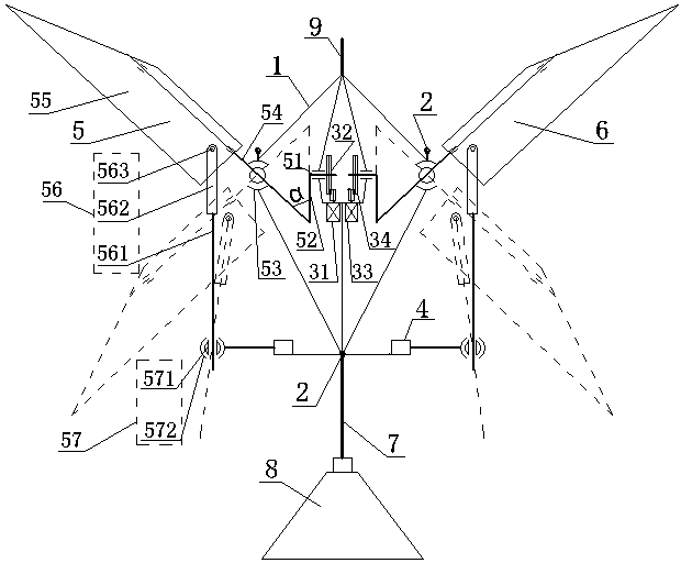
[0011] now attached figure 1 Example to illustrate the present invention: a conical rotary flapping wing aircraft includes a fuselage 1, landing gear 2, an energy system 3, a control system 4, a left conical rotary flapping wing 5, a right conical rotary flapping wing 6, and a tail boom 7 , empennage 8 and counterweight balance bar 9. The energy system 3 includes a left motor 31, a left reduction gear set 32, a right motor 33, a right reduction gear set 34, a convenient charging lithium battery and a motor speed control device; the control system 4 includes a radio navigation device and a steering gear; the fuselage 1 It is a frame structure made of carbon fiber composite material; the landing gear 2 is rear three-point type; the tail boom 7 is arranged horizontally, the front end of the tail boom 7 is connected to the tail of the fuselage 1, and the tail boom 8 is connected to the tail boom 7 through a steering gear of the control system 4 Connected to the rear end of the ta...


PUM


Abstract

The invention discloses a conical rotary flapping wing aircraft and belongs to the technical field of aircrafts. The conical rotary flapping wing aircraft is composed of an aircraft body, a landing gear, an energy system, a control system, a left conical rotary flapping wing, a right conical rotary flapping wing, a tail rod, a tail wing and a counterweight balancing rod, wherein the energy system comprises a left motor, a left speed reducing gear unit, a right motor, a right speed reducing gear unit, a conveniently charged lithium battery and a motor speed adjusting control device; the parameters of the left motor is the same as those of the right motor; the parameters of the left speed reducing gear unit is also the same as those of the right speed reducing gear unit; the control system comprises a wireless navigation device and a steering engine; the tail wing is used for balancing and controlling pitching flying postures; the structure of the left conical rotary flapping wing is the same as that of the right conical rotary flapping wing; the left and right conical rotary flapping wings are symmetrically arranged at the left and right sides of the aircraft body respectively and are used for providing push forces under the drives of the left and right motors respectively. The aircraft is capable of vertically lifting and hovering and can be applied to various tasks such as aerial photography, geographic survey, traffic duty, military reconnaissance, rescue and relief works when being provided with image shooting devices.

Description

technical field [0001] The utility model relates to a conical rotary flapping-wing aircraft, which belongs to the technical field of aircraft, and in particular relates to an aircraft with wings rotating. Background technique [0002] The traditional flapping wing aircraft relies on the crankshaft linkage mechanism to drive the flapping wings, and the flapping wings flutter up and down to generate thrust. Its efficiency is low, it is inconvenient to adjust the thrust direction, it is difficult to vertically lift, and the fatigue strength of the flapping wing material is relatively high. high. Contents of the invention [0003] The purpose of the present invention is to overcome the above-mentioned defect of traditional flapping-wing aircraft, and invent a conical rotary flapping-wing aircraft with higher efficiency and maneuverability. [0004] The present invention adopts the following technical scheme: a conical rotary flapping wing aircraft includes a fuselage, landing...

Claims


Application Information

Patent Timeline
Patent Type & Authority Applications(China)
IPC IPC(8): B64C33/00B64C33/02
Inventor 王志成
Owner 广州欣彩电脑耗材有限公司
Learn More