
Vehicle travelling control method and system

A travel control and travel direction technology, which is applied to control devices, vehicle components, external condition input parameters, etc. implementation control issues

Inactive Publication Date: 2014-08-20
BEIJING UNION UNIVERSITY
View PDF5 Cites 66 Cited by
  • Summary
  • Abstract
  • Description
  • Claims
  • Application Information

AI Technical Summary

Problems solved by technology

Under the premise that the road width is fixed or changes slowly, the system detects parallel lane lines with a certain width, which can be robust to shadows and occlusions, but this assumption is not suitable for roads with frequent width changes
It can be seen that due to the limitation of the calculation model used, this scheme will not be well applicable in non-ideal conditions such as many vehicles on the road, many events such as merging, irregular roads, and fast vehicle speeds.
[0006] It can be seen that for non-ideal conditions such as many vehicles on the road, frequent events such as merging lines, irregular roads, and fast vehicle speeds, the existing solutions cannot well deal with lane line occlusion and other problems that affect lane line recognition. In practical applications, there is a problem that the control of vehicle travel is not accurate enough, or even impossible to achieve control.
[0007] That is, for the emerging technical field of intelligent driving, there are many problems in the existing solutions for vehicle driving control, which cannot well adapt to the further development of intelligent driving technology and the actual application requirements

Method used


Image

  • Vehicle travelling control method and system
  • Vehicle travelling control method and system
  • Vehicle travelling control method and system

Examples


Embodiment Construction

[0076] In order to make the object, technical solution and advantages of the present invention clearer, the implementation manner of the present invention will be further described in detail below in conjunction with the accompanying drawings.

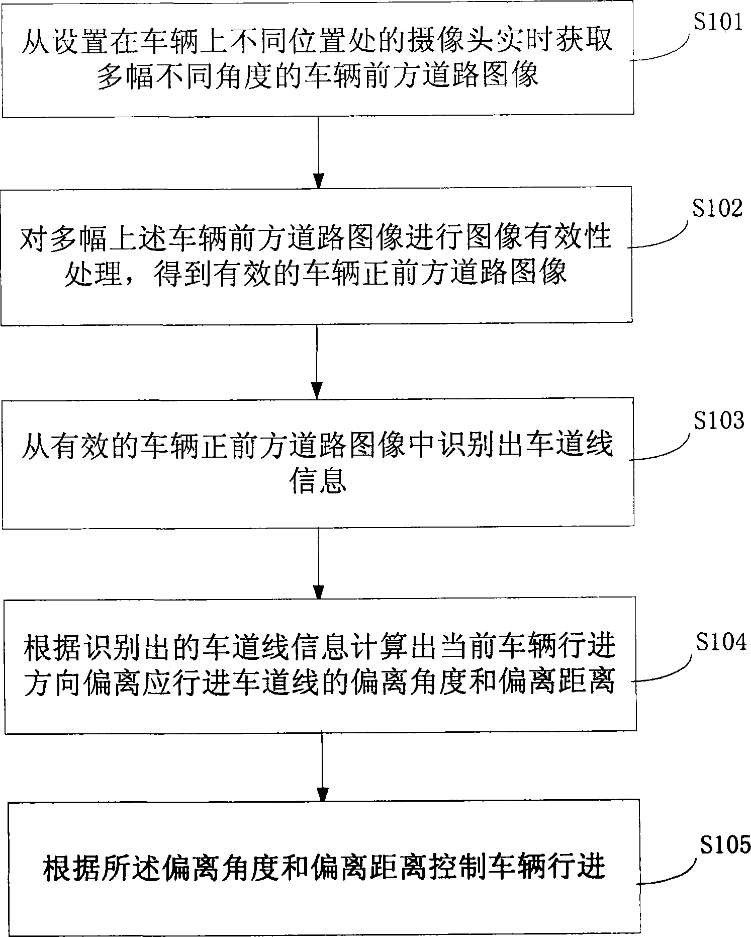
[0077] see figure 1 , an embodiment of the present invention provides a vehicle travel control method, which specifically includes the following steps:

[0078] S101: Obtain multiple images of the road ahead of the vehicle from different angles in real time from cameras set at different positions on the vehicle.

[0079] A vehicle driving control method implemented in the embodiment of the present invention requires a camera to be installed on the controlled vehicle to acquire the road image in front of the vehicle, and then recognize lane line information therefrom, and control the vehicle to run normally.

[0080] It should be noted that if only one camera is installed on the vehicle, or multiple cameras are only installed at simila...


PUM


Abstract

The invention discloses a vehicle travelling control method and system, and relates to the technical field of automatic control. Multiple road images at different angles in front of a vehicle are obtained in real time from cameras arranged on different positions of the vehicle, effective road images dead ahead the vehicle are obtained after processing of the images, lane line information is recognized from the road images dead ahead the vehicle, the deviation angle and the deviation distance between the current vehicle traveling direction and a required lane line are calculated, and the vehicle is further controlled to travel according to the deviation angle and the deviation distance. Complex formula calculations can be avoided, efficiency is improved, missed information can be obtained according to actual images, accuracy is further improved, the scheme is simple and efficient, the control is accurate and free of limiting of application scenes, images at multiple angles can be obtained conveniently under the complex conditions that many vehicles are on roads, parallel line travelling occurs frequently, the roads are not standard, the vehicle speed is high and the like, adaptability to multiple scenes is higher, and automatic control over the vehicles can be achieved better.

Description

technical field [0001] The invention relates to the technical field of automatic control, in particular to a vehicle travel control method and system. Background technique [0002] Intelligent driving technology involves cognitive engineering, vehicle engineering, electrical and electronic engineering, control science and engineering, artificial intelligence and many other disciplines. Intelligent vehicles are an important symbol to measure a country's scientific research strength and industrial level. The emergence of unmanned vehicles has fundamentally changed the vehicle driving mode in the traditional "human-vehicle-road" closed-loop system, liberating the driver from fatigue driving, using advanced sensors and information technology to control vehicle driving, Automating routine, long-lasting, low-level, and repetitive operations in driving activities can greatly improve the efficiency and safety of the transportation system, improve the quality of human mobile life, an...

Claims


Application Information

Patent Timeline
IPC IPC(8): B60W30/12B60W40/10B60W40/06B60R11/04
CPCB60R11/04B60W30/12B60W40/06B60W40/10B60W2552/00
Inventor 刘佳刘宏哲钮文良郑永荣李鑫铭马耀昌
Owner BEIJING UNION UNIVERSITY
Learn More