
Rotational multi-workpiece clamping and multi-station pneumatic clamp

A pneumatic fixture, multi-station technology, applied in the direction of manufacturing tools, clamping, positioning devices, etc., can solve the problems of low processing efficiency, troublesome operation, and many times of loading and unloading, and achieve the effect of improving production efficiency

Inactive Publication Date: 2014-08-20
ANHUI TECHN COLLEGE OF MECHANICAL & ELECTRICAL ENG
View PDF10 Cites 33 Cited by
  • Summary
  • Abstract
  • Description
  • Claims
  • Application Information

AI Technical Summary

Problems solved by technology

[0002] The field of modern mechanical numerical control machining is more and more oriented towards mass customization and mass-scale production. In the automobile and other manufacturing industries, there are often various polyhedral multi-station processing requirements for valve bodies, pump bodies and cylinder blocks. Although the three-axis and five-axis machining centers can realize multi-station machining of workpieces in one clamping, they are not suitable for mass production mode. The use of three-axis machining centers with good cost performance requires multiple clamping of workpieces to complete multi-station surface processing, resulting in loading and unloading problems. Too many times and cumbersome operations lead to low processing efficiency, and the cumulative error caused by multiple clampings affects the processing quality of the workpiece

Method used


Image

  • Rotational multi-workpiece clamping and multi-station pneumatic clamp
  • Rotational multi-workpiece clamping and multi-station pneumatic clamp
  • Rotational multi-workpiece clamping and multi-station pneumatic clamp

Examples


Embodiment

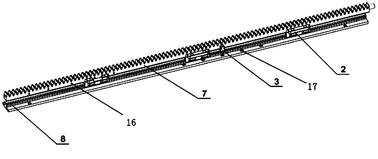
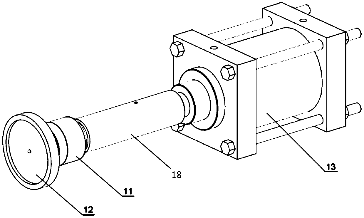
[0023] refer to Figure 1~Figure 4 , the present invention is a pneumatic clamp capable of fulfilling the requirements of six workpiece clamping and four station rotation positioning, including a clamp body 1 with two parallel vertical vertical plates 15; a vertical vertical plate installed on one side of the clamp body 1 15 positioning and rotating mechanism, the positioning and rotating mechanism is composed of driving cylinder 14, rack 7, slide block 2, guide rail 8, limit switch 3, positioning cylinder 6, cylindrical gear 4, rotating shaft 5 and positioning plate for positioning the workpiece, positioning The clamping mechanism installed on the vertical vertical plate 15 on the other side of the clamping body 1 is composed of components such as the clamping cylinder 13, the rolling ejector rod 11 and the briquetting block 12.

[0024] In order to ensure that the position of the fixture on the machine table is accurate, two orientation keys 9 are installed on the bottom of ...


PUM


Abstract

The invention discloses a rotational multi-workpiece clamping and multi-station pneumatic clamp. The clamp comprises a clamp body, a locating rotating mechanism and a clamping mechanism, wherein the clamp body comprises two vertical boards parallel to each other, and the two vertical boards are provided with the locating rotating mechanism and the clamping mechanism respectively and are connected with each other through a plurality of pull rods; the locating rotating mechanism comprises a driving air cylinder, an output shaft of the driving air cylinder is connected with a toothed bar located on one side of one vertical board, the vertical boards are evenly provided with a plurality of rotary shafts, each rotary shaft is connected with a cylindrical gear through a key, and each cylindrical gear is meshed with the toothed bar; the clamping mechanism comprises a plurality of clamping air cylinders which are respectively in transmission connection with a rolling jacking rod, each rolling jacking rod penetrates through the other vertical board, and a pressing block is fixed to the other end of each rolling jacking rod. The rotational multi-workpiece clamping and multi-station pneumatic clamp can effectively achieve the function of a numerically-controlled machine tool, improve machining efficiency of workpieces, and guarantee machining quality.

Description

technical field [0001] The invention belongs to the field of fixture design of numerical control machine tools, and in particular relates to a multi-piece clamping and multi-station rotatable pneumatic fixture. Background technique [0002] The field of modern mechanical numerical control machining is more and more oriented towards mass customization and mass-scale production. In the manufacturing industries such as automobiles, there are often various polyhedral multi-station processing requirements for valve bodies, pump bodies, and cylinder blocks. Although the three-axis and five-axis machining centers can realize multi-station machining of workpieces in one clamping, they are not suitable for mass production mode. The use of three-axis machining centers with good cost performance requires multiple clamping of workpieces to complete multi-station surface processing, resulting in loading and unloading problems. Many times and troublesome operation lead to low processing e...

Claims


Application Information

Patent Timeline
IPC IPC(8): B23Q3/08B23Q15/26
CPCB23Q3/08B23Q3/061B23Q15/26B23Q2703/04B23Q2703/08
Inventor 张国政李嘉翔胡涛赵文英刘顺周元枝
Owner ANHUI TECHN COLLEGE OF MECHANICAL & ELECTRICAL ENG
Learn More