
Hall Effect Thrusters

A Hall effect, thruster technology, used in aircraft, thrust reversers, machines/engines, etc.

Active Publication Date: 2017-03-29
SN DETUDE & DE CONSTR DE MOTEURS DAVIATION (S N E C M A)
View PDF6 Cites 1 Cited by
  • Summary
  • Abstract
  • Description
  • Claims
  • Application Information

AI Technical Summary

Problems solved by technology

However, the manipulation of thrust through the uneven flow rate of the gas injected into the annular channel described in these documents is relatively ineffective and even frustrating considering the additional complexity introduced by the flow regulator device

Method used


Image

  • Hall Effect Thrusters
  • Hall Effect Thrusters
  • Hall Effect Thrusters

Examples


Embodiment Construction

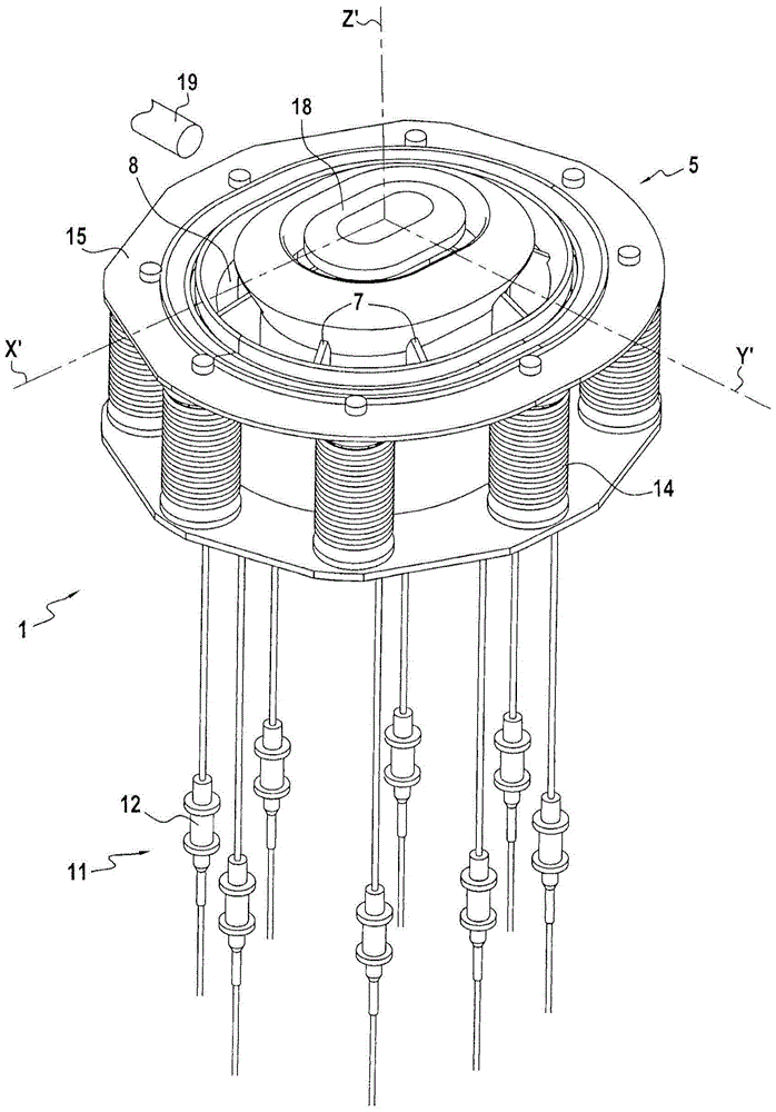
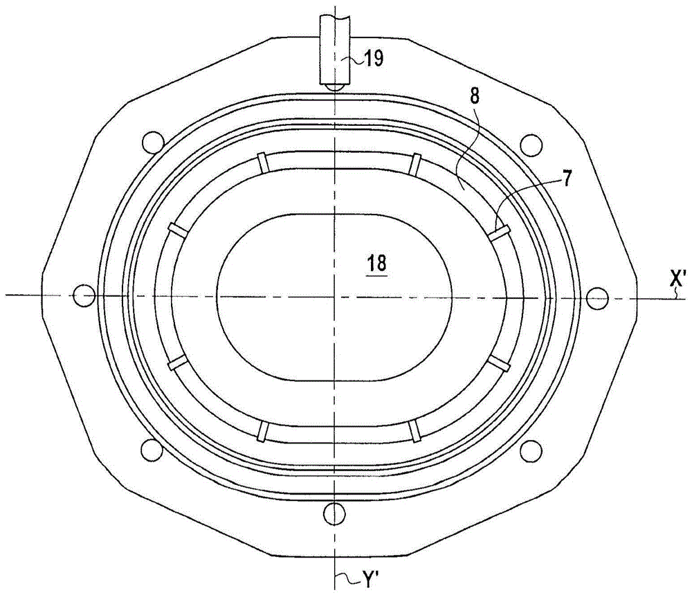
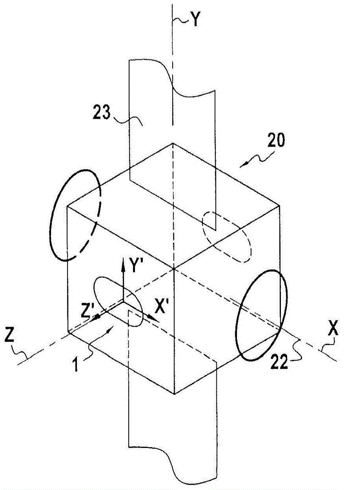
[0027] figure 1 , Figure 1A and Figure 1B Different views of the same Hall effect thruster 1 in an embodiment are shown. The propeller 1 has an annular channel 2 defined by two concentric walls 3, 4 around the central axis Z', these concentric walls being made of ceramic material. The annular channel 2 has an open end 5 and a closed end 6 . Next to the closed end 6 , a radial wall 7 subdivides the upstream section 2 a of the annular channel 2 into separate compartments 8 . At the closed end 6 , the annular channel 2 also has an anode 9 which can be separated from a plurality of compartments 8 and a nozzle 10 for injecting propellant gas into each compartment 8 . The nozzles 10 are connected to a source of propellant gas by means of injection circuits 11 comprising separate flow rate regulator means 12 for each nozzle 10 . For example, each device 12 may be a pencil valve or a thermo-capillary; a thermo-capillary, ie a capillary with a heating device capable of actively ...


PUM


Abstract

The invention relates to a Hall-effect thruster, in particular a Hall-effect thruster (1) with tiltable thrust, wherein the final stage of the magnetic circuit comprises an inner pole (18) which is opposite to the outer pole (15) is axially offset downstream such that said magnetic field (M) is inclined with respect to the cross-section of the propeller (1).

Description

technical field [0001] The present invention relates to the field of Hall effect thrusters. [0002] The present invention more particularly relates to a steerable thrust Hall effect thruster having an annular channel, an anode, an injection circuit, a magnetic circuit and a cathode. The annular channel is defined by two concentric walls having a central axis, has an open end and a closed end, and includes an upstream section adjacent to the closed end, which is subdivided by radial walls into a plurality of separate compartments . The anode is located at the closed end of the annular channel. The injection circuit is adapted to inject propellant gas, such as for example xenon, into the compartments of the annular channel and comprises at least one independent flow regulator means for each compartment. The magnetic circuit is adapted to form a magnetic field at the open end of the annular channel. The cathode is located outside the open end of the annular channel. [0003...

Claims


Application Information

Patent Timeline
Patent Type & Authority Patents(China)
IPC IPC(8): F03H1/00
CPCF03H1/0075B64G1/405F03H1/0068F03H1/0062F03H1/0006
Inventor F·R·J·玛彻德斯安东尼·克劳得·博纳德·洛兰V·M·韦尔
Owner SN DETUDE & DE CONSTR DE MOTEURS DAVIATION (S N E C M A)
Learn More