Braking switch valve and method for switching operation state of locomotive by same

A technology for manipulating the state and switching valves, applied in the direction of brakes, brake components, pneumatic brakes, etc., can solve problems such as difficult wiring, complex structure, and influence on system pipeline design, so as to save installation quantity and space, and facilitate inspection and maintenance , the direct effect of manipulation

Inactive Publication Date: 2011-06-08
CRRC QINGDAO SIFANG CO LTD
View PDF0 Cites 0 Cited by
  • Summary
  • Abstract
  • Description
  • Claims
  • Application Information

AI Technical Summary

Problems solved by technology

The dual control devices with the same configuration structure and functions not only affect the design of the system pipeline, make the structure complex, and make wiring difficult, but also bring inconvenience to the inspection and maintenance of the locomotive due to the limitation of the installation space of the brake device.

Method used


Image

  • Braking switch valve and method for switching operation state of locomotive by same
  • Braking switch valve and method for switching operation state of locomotive by same
  • Braking switch valve and method for switching operation state of locomotive by same

Examples


Embodiment 1

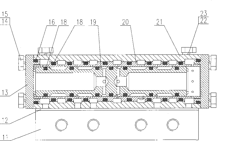
[0034] Example 1, such as Figure 1 to Figure 4 As shown, the brake switching valve has a valve body 21 , and end caps 13 are arranged at both ends of the valve body 21 . in,

[0035] A valve sleeve 20 is disposed in the inner cavity of the valve body 21 , and a plunger valve 19 that can reciprocally slide toward the end caps 13 on both sides is disposed in the inner cavity of the valve sleeve 20 . The valve body 21 is connected with the vehicle body floor through the valve seat 11 . An O-ring 16 for sealing is arranged between the valve sleeve 20 and the valve body 21 . Several O-rings 18 for sealing are arranged outside the plunger valve 19 .

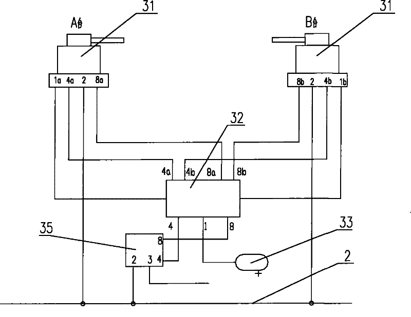
[0036] The brake switching valve 32 is connected to two brake valves 31 , a relay valve 35 and an equalizing air cylinder 33 , respectively. specifically,

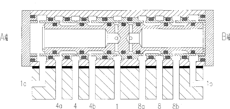
[0037] There are 9 annular channels between the valve sleeve 20 and the valve body 21, including the first equalizing air cylinder pipe 1 connected to the equalizing air cyli...


PUM


Abstract

The invention provides a braking switch valve and a method for switching the operation state of a locomotive by same. Under the precondition that the work principle of a braking system and the air pipeline structure of the prior locomotive are not changed, a switch is used between two operation tables, and one set of brake is used for switching the operation between the two operation tables of a control chamber by changing the direction of the automatic communicating and switch-off state of pressure air in the switch to realize the purposes of saving the installation space of the brake part and improving overhaul and maintenance convenience. The braking valve is provided with a valve body, and both ends of the valve body are respectively provided with an end lid. A valve sleeve is sleevedin the internal cavity of the valve body, and a plurality of through slots which are communicated with an external device are arranged between the valve sleeve and the valve body. A plunger piston valve capable of sliding towards the end lids on both ends in a reciprocating mode is arranged in the internal cavity of the valve sleeve. The valve body is connected with a soleplate of the vehicle bodyby the valve base.

Description

technical field [0001] The invention relates to a brake manipulation switching device and a realization method thereof, which are applied to a rail vehicle locomotive brake control system. Background technique [0002] Most locomotives currently used in railway shunting operations are equipped with dual consoles, so that the driver can perform shunting operations in the front and rear directions. [0003] Existing locomotive braking system generally adopts air brake, and also will be equipped with two sets of identical braking devices in the cab, including two sets of braking valves, relay valves and equalizing air cylinders. The dual control devices with the same configuration structure and functions not only affect the design of the system pipeline, make the structure complex and difficult to route, but also bring inconvenience to the inspection and maintenance of the locomotive due to the limitation of the installation space of the brake device. Contents of the inventio...

Claims


Application Information

Patent Timeline
Patent Type & Authority Patents(China)
IPC IPC(8): B60T13/24B60T15/04B61H11/06
Inventor 张立国赖森华杨昌锋吴冬华
Owner CRRC QINGDAO SIFANG CO LTD
Why Eureka
Try Eureka