A hinged prefabricated hollow slab girder bridge hinged joint and its construction method

A hollow slab beam and construction method technology, applied in bridges, bridge construction, erection/assembly of bridges, etc., can solve the problems of complex stress, imperfect design theory, unfavorable structure, etc. Crack resistance, reducing the stress phenomenon of veneer, reducing the effect of longitudinal cracks on the bridge deck

Inactive Publication Date: 2015-10-14
FUZHOU UNIV
View PDF4 Cites 0 Cited by
  • Summary
  • Abstract
  • Description
  • Claims
  • Application Information

AI Technical Summary

Problems solved by technology

However, there are still some problems: the hinged concrete cracks and falls off, and in severe cases, it peels off in blocks; at the same time, there is serious water seepage, which may corrode the steel bars of the beam and slab; what's more, the stress on the single plate seriously affects the normal use of the bridge , reduce the service life; and the current design theory is not perfect enough, the consideration is not yet comprehensive, and the existing problems cannot be solved well
In general articulated prefabricated hollow slab girder bridges, due to the weak horizontal connection, it is easy to form longitudinal reflection cracks between the prefabricated beams visible to the naked eye, which not only affects the appearance, but also forms unfavorable potholes in serious cases, and at the same time, water seeps into the surface of the cracks In concrete, the concrete at the lower part of the hinge joint will peel off, etc., and in severe cases, the hinge joint connection will fail, and the single-slab stress phenomenon that is unfavorable to the structure will appear.
The actual force of the hinged joint is complicated, but in the existing design, not only the tension (compression) of the hinged joint is ignored in the calculation theory of the hinged plate, but also there is a certain difference between the calculation diagram of the hinged joint shear and the actual force. There is actually a certain bending effect in the

Method used


Image

  • A hinged prefabricated hollow slab girder bridge hinged joint and its construction method
  • A hinged prefabricated hollow slab girder bridge hinged joint and its construction method

Examples


Embodiment Construction

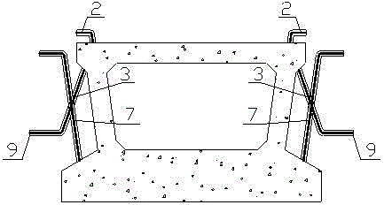
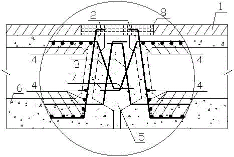
[0025] Such as Figure 1~2 As shown, a hinged prefabricated hollow slab girder bridge hinge joint includes a plurality of prefabricated hollow slab girders 6, and hinge joints 5 are formed between two adjacent hollow slab girders 6, and cement is poured into the hinge joints 5 slurry, above the hollow slab girder 6 and hinge joint 5, a bridge deck pavement layer is poured, the upper part of the hollow slab girder 6 is pre-embedded with the upper transverse reinforcement 3, and the lower part of the hollow slab girder 6 is pre-embedded with The lower transverse steel bar 2 and the reinforcing steel bar 7 located on the upper side of the lower transverse steel bar 2, the outer end of the upper transverse steel bar 3 protrudes from the side of the hollow plate beam 6 and bends downwards and extends into the hinge joint 5 for anchoring. The reinforcing steel bar The outer end of 7 protrudes from the side of the hollow plate beam 6 and bends upwards and extends into the hinge joint...


PUM


Abstract

The invention relates to a novel articulated prefabricated hollow slab girder bridge hinge joint connector and a construction method thereof. The hinge joint connector comprises a plurality of prefabricated hollow slab girders; a hinge joint is formed between every two adjacent hollow slab girders; cement paste fills in the hinge joints; a bridge deck pavement layer is poured above the hollow slab girders and the hinge joints; upper transverse reinforcements are embedded in the upper parts of the hollow slab girders; lower transverse reinforcements and reinforcing reinforcements which are located at the upper sides of the lower transverse reinforcements are embedded in the lower parts of the hollow slab girders; the outer ends of the upper transverse reinforcements stretch out of the side faces of the hollow slab girders and are downwards bent to stretch into the hinge joints; the outer ends of the reinforcing reinforcements stretch out of the side faces of the hollow slab girders and are upwards bent to stretch into the hinge joints; the stretching sections of the upper transverse reinforcements and the stretching sections of the reinforcing reinforcements intersect in the hinge joints; the outer ends of the lower transverse reinforcements are upwards bent to stretch out of the top surfaces of the hollow slab girders and stretch into the bridge deck pavement layer above the hinge joints. The novel articulated prefabricated hollow slab girder bridge hinge joint connector and the construction method thereof have the advantage that the shear resisting performance, the anti-cracking performance and the resistance to bending of the hinge joints are improved.

Description

technical field [0001] The invention relates to a hinge joint of a hinged prefabricated hollow slab girder bridge and a construction method thereof, belonging to the technical field of bridges. Background technique [0002] The hinged prefabricated hollow slab girder bridge has the following advantages: (1) simple design; (2) low cost in the life cycle; (3) simple and fast construction; (4) high degree of industrialization. In conclusion, this kind of bridge is widely used because of its high bearing capacity, good durability, attractive appearance and low height-to-span ratio. However, there are still some problems: the hinged concrete cracks and falls off, and in severe cases, it peels off in blocks; at the same time, there is serious water seepage, which may corrode the steel bars of the beam and slab; what's more, the stress on the single plate seriously affects the normal use of the bridge , to reduce the service life; and the current design theory is not perfect, and ...

Claims


Application Information

Patent Timeline
Patent Type & Authority Patents(China)
IPC IPC(8): E01D2/04E01D21/00
CPCY02A30/30
Inventor 庄一舟陈斌陈云韩裕添
Owner FUZHOU UNIV
Why Eureka
Try Eureka