Oil tank bracket machining die

A technology for processing molds and brackets, which is used in the field of processing molds for fuel tank brackets, can solve the problems of weakened cross-section and brittle fracture of components, and achieve the effects of reducing workload, improving service life and reducing friction.

Inactive Publication Date: 2014-08-13
CHENGDU LINGCHUAN SPECIAL IND
View PDF7 Cites 0 Cited by
  • Summary
  • Abstract
  • Description
  • Claims
  • Application Information

AI Technical Summary

Problems solved by technology

[0003] The traditional fuel tank bracket usually uses a bending die to process the steel. First of all, the bracket is not suitable for bending and then punching because of the large depth of the edge. Therefore, the steel is punched first, and then the steel is bent. But The above problems are prone to occur in the traditional bending process, that is, after the bending of the bracket is welded to the fuel tank, the fuel tank is prone to form stress concentration points at the bending of the bracket during work, and there may be welding defects , micro-cracks are gradually generated at stress concentration points and welding defects, forming fatigue sources. As the mileage increases, the cracks gradually expand, and the cross-section of the component is gradually weakened, so that it cannot bear the applied load and suddenly brittle fracture occurs

Method used


Image

  • Oil tank bracket machining die
  • Oil tank bracket machining die

Examples


Embodiment 1

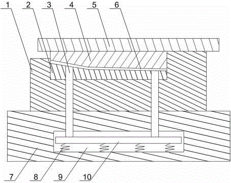
[0021] Such as figure 1 and figure 2 As shown, the fuel tank bracket processing mold of the present invention comprises an upper mold base 5 and a lower mold base 7, a punch 4 is installed on the upper mold base 5, a die 1 is installed on the lower die base 7, and the die base 7 is installed on the die base 7. 1 is installed with a forming block 2, the upper surface of the forming block 2 is two interconnected inclined surfaces, the forming block 2 is provided with a forming groove 11, and a discharge cavity 9 is provided in the lower mold base 7. A baffle 10 is installed inside the body 9, and the baffle 10 is connected to the bottom of the discharge cavity 9 through a spring 8, and a discharge rod 3 is installed on the baffle 10, and the discharge rod 3 runs through the lower mold base 7, the die 1 and molding block 2 and are higher than the bottom of molding groove 11. When the present invention is working, the upper die base 5 is separated from the lower die base 7 driv...

Embodiment 2

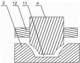
[0023] Such as figure 1 and figure 2 As shown, this embodiment is based on Embodiment 1, the groove wall of the forming groove 11 is arc-shaped, and the groove width of the forming groove 11 gradually decreases along the vertical direction. The two walls of the forming groove 11 are protruding circular arcs, so that the groove width of the forming groove 11 decreases gradually along the vertical direction, and the smooth circular arc surface can reduce the friction force of the steel plate moving down in the groove and reduce the pressure of the punch 4 times. The resistance to shifting can reduce the workload of the driving equipment during the bending process of the steel plate, and indirectly reduce the production cost.

Embodiment 3

[0025] Such as figure 2 As shown, this embodiment is based on Embodiment 1, the punch 4 is a trapezoidal block matching the forming groove 11, and leveling plates 12 are installed on both sides of the trapezoidal block. The punch 4 matches the profile of the forming groove 11, and the steel plate can be bent into the required shape. The flat plate 12 installed on both sides of the trapezoidal block can make the steel plate form a supporting surface, and the supporting surface increases the bracket and The contact area of ​​the fuel tank ensures the stability of the fuel tank during use.


PUM


Abstract

The invention discloses an oil tank bracket machining die. The oil tank bracket machining die comprises an upper die seat and a lower die seat, wherein the upper die seat is provided with a male die, the lower die seat is provided with a female die, a shaping block is mounted in the female die, upper surfaces of the shaping block are two inclining faces which are connected with each other, a shaping groove is formed in the shaping block, a discharging cavity is formed in the lower die seat, a stop plate is mounted in the discharging cavity and connected with the bottom of the discharging cavity via springs, and discharging rods penetrating through the lower die seat, the female die and the shaping die and higher than the bottom of the shaping block are mounted on the stop plate. By the aid of the two connected inclining faces, a steel sheet can be stressed integrally, so that the steel sheet can be uniformly stressed during machining, partial stress concentration at bending positions of shaped bracket blanks is lowered, bracket are protected from fatigue sources resulted from tiny cracks at the welded bending positions of the bracket in the usage process after the bracket is welded with an oil tank, and service life of the oil tank bracket is prolonged.

Description

technical field [0001] The invention relates to a bending structure, in particular to a mold for processing an oil tank bracket. Background technique [0002] The vehicles with damaged fuel tank brackets are mainly tractors, and the running roads are generally above the secondary road conditions. When the vehicles travel about 7000km, there are batches of hidden dangers of cracks or fractures. During the operation of the fuel tank bracket, it mainly bears the mass load of the fuel tank, and at the same time, it will be affected by the dynamic load coefficient, that is, the impact of the road surface, which makes the stress environment of the fuel tank bracket worse. The failure of the fuel tank bracket was preliminarily judged to be fatigue fracture. Since the bracket was welded by two pieces of "several" steel, there was no external reinforcement plate at the welding position, which was relatively weak, and it was subjected to impact loads during work, which eventually led ...

Claims


Application Information

Patent Timeline
Patent Type & Authority Applications(China)
IPC IPC(8): B21D37/10
Inventor 汪庭文叶维敏张军何晓鸣杨军
Owner CHENGDU LINGCHUAN SPECIAL IND
Why Eureka
Try Eureka