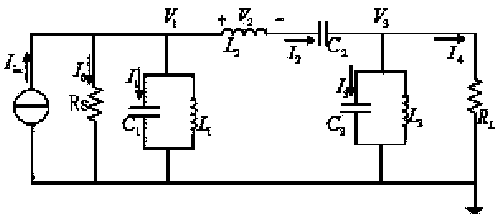
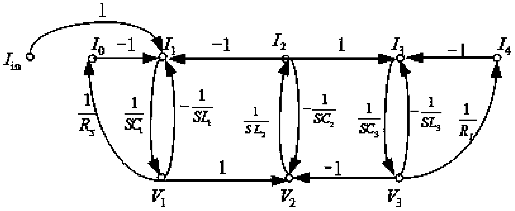
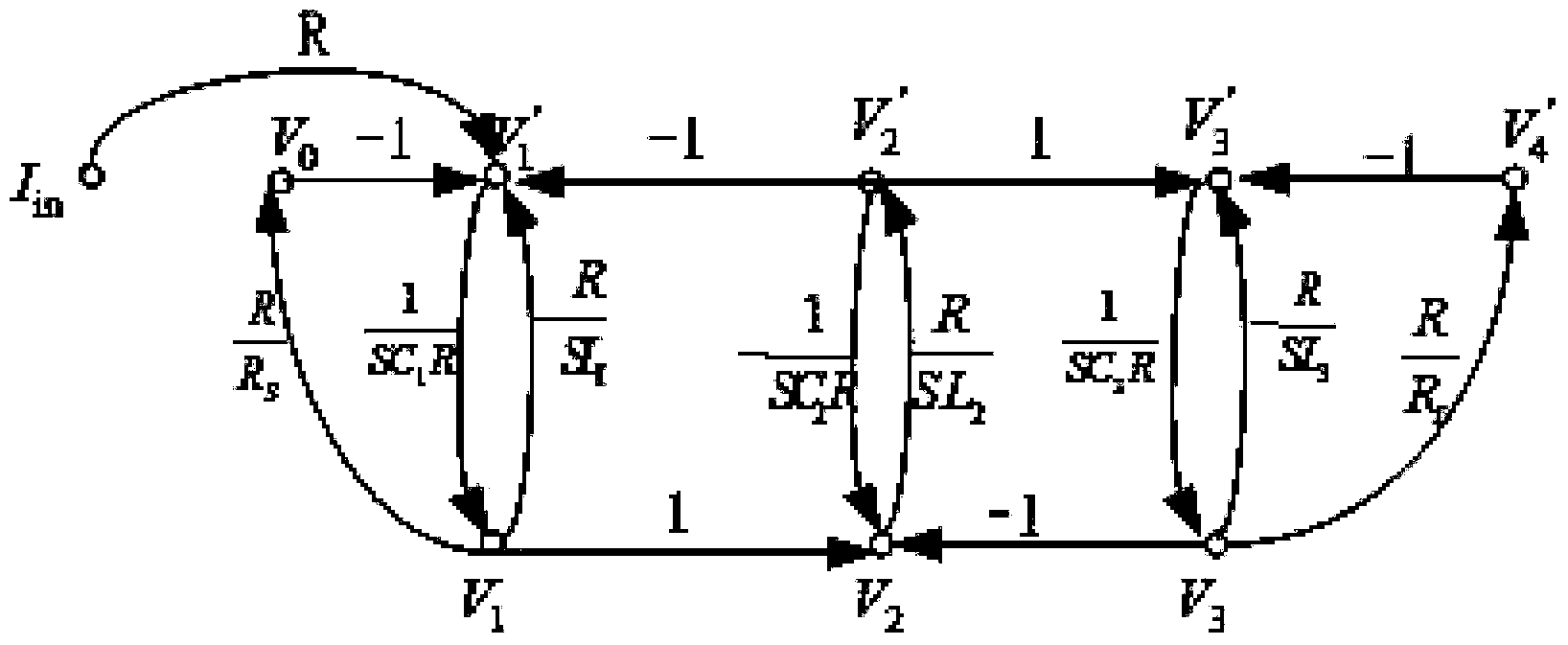
Transimpedance type integrated band-pass filter design method
A band-pass filter and filter design technology, applied in the direction of impedance network, electrical components, multi-terminal pair network, etc., can solve the problems of complex design process and high sensitivity to component changes, and achieve low power consumption, low sensitivity, large Effect of the dynamic range filter
- Summary
- Abstract
- Description
- Claims
- Application Information
AI Technical Summary
Problems solved by technology
Method used
Image
Examples
Embodiment 1
[0066] A specific embodiment of the present invention adopts signal flow diagram method to design a transimpedance type band-pass filter, and its technical index is:
[0067] Lower passband cutoff frequency: f 1 =0.67MHz, upper pass band cut-off frequency: f u =1.5MHz;
[0068] Stop band lower limit cut-off frequency: f s1 =0.4MHz, stop band upper limit cut-off frequency: f su =2.5MHz;
[0069] The maximum attenuation allowed by the passband: A max =1dB, the minimum attenuation allowed by the stop band: A min =20dB;
[0070] R S =R L =10KΩ.
[0071] After frequency conversion, the amplitude-frequency characteristics of the low-pass filter can be obtained.
[0072] Exploitation =1, , the normalized technical index of the low-pass filter can be calculated as:
[0073] Passband cut-off frequency f p =1Hz, the maximum attenuation allowed by the passband: A max =1dB,
[0074] Stop band cut-off frequency: f s =2.53Hz, the minimum attenuation allowed by the stop ba...
PUM
 Abstract
Description
Claims
Application Information
 - R&D
- Intellectual Property
- Life Sciences
- Materials
- Tech Scout
- Unparalleled Data Quality
- Higher Quality Content
- 60% Fewer Hallucinations
Browse by: Latest US Patents, China's latest patents, Technical Efficacy Thesaurus, Application Domain, Technology Topic, Popular Technical Reports.
© 2025 PatSnap. All rights reserved.Legal|Privacy policy|Modern Slavery Act Transparency Statement|Sitemap|About US| Contact US: help@patsnap.com


