
A support shear differential compensation connection device

A technology for connecting devices and repairing boards, which is applied in the direction of measuring devices, instruments, scientific instruments, etc., can solve problems such as lengthening the test cycle, potential safety hazards of equipment and personnel, and flawed test results, so as to reduce the test cycle and test cost. Ensure accuracy and completeness, avoid rework effects

Active Publication Date: 2016-09-07
BEIJING UNIV OF TECH
View PDF3 Cites 0 Cited by
  • Summary
  • Abstract
  • Description
  • Claims
  • Application Information

AI Technical Summary

Problems solved by technology

Due to the variety of support types, the diameter and hole position of the mounting holes are even more diverse. For each type of support, a transition connection plate matching the mounting hole must be processed, which greatly lengthens the test cycle and increases the test cost. ; Since the diameter of the connecting bolt is smaller than the diameter of the mounting hole, and the shear force in the test is often greater than the friction between the support and the transition plate, the transition plate and the shear slide plate, once the relative slip occurs between the friction surfaces, the connection The impact shear of the bolts is easy to cut the bolts, causing potential safety hazards for equipment and personnel. Second, it affects the test results, causing flaws or even failures in the test results.

Method used


Image

  • A support shear differential compensation connection device
  • A support shear differential compensation connection device
  • A support shear differential compensation connection device

Examples


Embodiment Construction

[0016] The present invention will be further described below in conjunction with the accompanying drawings and specific embodiments.

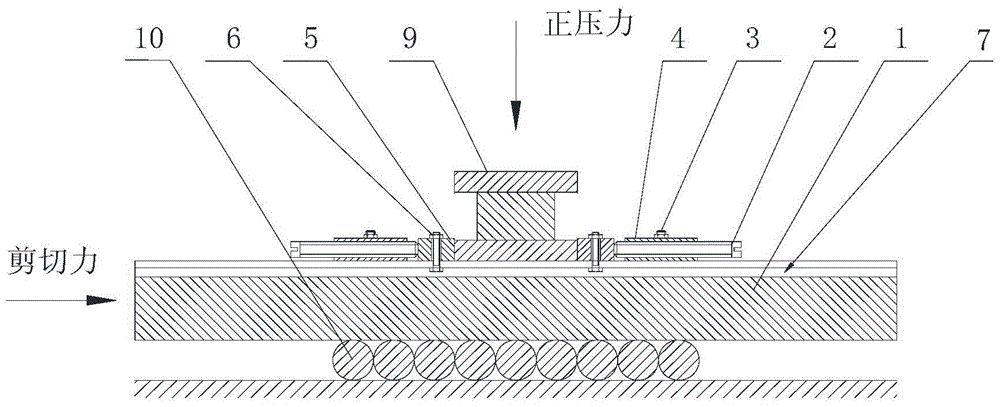
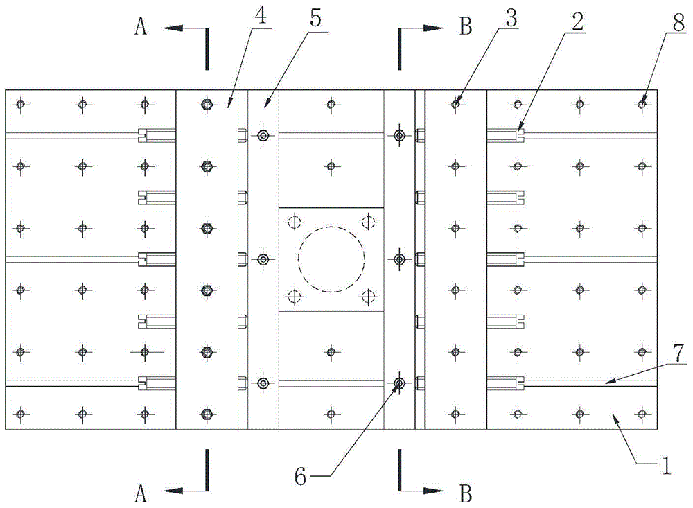
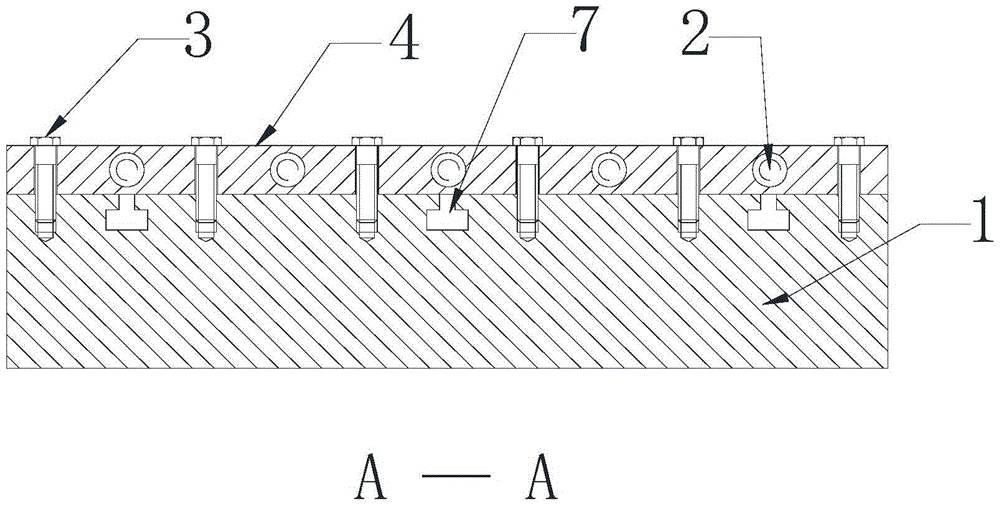
[0017] Such as figure 1 The shown one kind of support anti-shear differential compensation connection device includes shear slide plate 1, jacking bolt 2, anchor plate bolt 3, anchor plate 4, differential compensation plate 5, differential compensation bolt 6, dovetail groove 7, anchor Bolt holes 8; evenly distributed anchor bolt holes 8 are arranged on the shear slide 1; two anchor plates 4 are laid on the shear slide 1, and are fixed on the shear slide 1 by the anchor plate bolts 3; The difference patching plate 5 is placed between the test supports 9; the anchor plate 4 is provided with a threaded through hole along the shearing direction, and the jacking bolt 2 is screwed in through the threaded through hole, and the difference patching plate 5 is pressed tightly to provide shear for the test of the support 9. Cut reaction force.

[0018]...


PUM


Abstract

The invention relates to a shearing resistant difference-supplementing connecting device for a support, and belongs to a structure experiment technology. The shearing resistant difference-supplementing connecting device for the support comprises a shearing slide plate 1, propping and fixing bolts 2, anchor plate bolts 3, anchor plates 4, difference-supplementing plates 5, difference-supplementing bolts 6, a dovetail groove 7, and anchor bolt holes 8, wherein the two anchor plates are paved on the shearing slide plate 1 with the uniformly distributed anchor bolt holes 8, and are fixed on the shearing slide plate 1 through the anchor plate bolts 3; each difference-supplementing plate 5 is placed between each anchor plate and the support 9 to be detected; threaded through holes are formed in the anchor plates in the shearing direction; the propping and fixing bolts are screwed inwards through the threaded through holes to be propped against the difference-supplementing plates, so that shearing counter force can be provided for the test of the support 9. According to the invention, the anchor plates and the difference-supplementing plates are placed on the shearing slide plate, so that the repeated processing of a connecting plate can be avoided, further, the test cycle and test cost can be reduced, the safety of the personnel and equipment can be guaranteed, and the accuracy and integrity of the testing result can be ensured.

Description

Technical field: [0001] The invention relates to a support shear differential compensation connection device, which is used for fixing the support in the shear direction in the support shear test and providing the reaction force required by the shear test. Background technique: [0002] In the shear test of the support, it is often connected with the shear slide plate by connecting bolts through the mounting holes of the connecting plate of the support itself. Due to the variety of support types, the diameter and hole position of the mounting holes are even more diverse. For each type of support, a transition connection plate matching the mounting hole must be processed, which greatly lengthens the test cycle and increases the test cost. ; Since the diameter of the connecting bolt is smaller than the diameter of the mounting hole, and the shear force in the test is often greater than the friction between the support and the transition plate, the transition plate and the shea...

Claims


Application Information

Patent Timeline
Patent Type & Authority Patents(China)
IPC IPC(8): G01N3/02
Inventor 纪金豹陈利民李芳芳李小军张硕玉
Owner BEIJING UNIV OF TECH
Learn More