
Roller brush speed control system for pavement sweeping machine

A sweeper and roller brush technology, applied in road cleaning, mechanical equipment, cleaning methods, etc., can solve problems such as low speed, and achieve the effect of strong practicability and advancement, and a wide range of use.

Active Publication Date: 2014-08-06
宁波新合博园林机械有限公司
View PDF5 Cites 2 Cited by
  • Summary
  • Abstract
  • Description
  • Claims
  • Application Information

AI Technical Summary

Problems solved by technology

The speed of the roller brush of the traditional road sweeper is constant. For different cleaning objects, the roller brush of the sweeper needs different speeds. It needs a low speed when cleaning garbage, and a relatively high speed when cleaning snow. In view of this , the applicant provides a roller brush speed change system for road sweepers, and this case arises from this

Method used


Image

  • Roller brush speed control system for pavement sweeping machine
  • Roller brush speed control system for pavement sweeping machine
  • Roller brush speed control system for pavement sweeping machine

Examples


Embodiment Construction

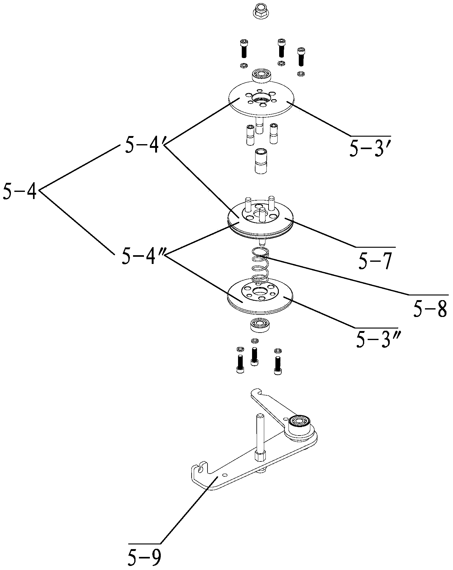
[0016] Such as figure 1 , 2 , 3, 4, and 5, what the present invention discloses is a roller brush speed change system for a road sweeper, including a drive pulley 3, a belt clutch control assembly 4, a variable speed pulley control assembly 5, a roller brush pulley 11, a roller Brush variable speed control assembly 1 and roller brush starting assembly 2; wherein, the variable speed pulley control assembly 5 includes an upper pulley 5-4' and a lower pulley 5-4" that rotate around the same central axis The pulley group 5-4, the drive pulley 3 is connected with the lower pulley 5-4" through the primary transmission belt 9, and the roller brush pulley 11 is connected with the upper pulley 5-4' through the secondary transmission belt 10; the belt clutch control assembly 4 is located on the primary transmission belt 9, the roller brush starting assembly 1 is connected through the first cable 12 and controls the belt clutch control assembly 4, and the variable speed pulley control a...


PUM


Abstract

The invention belongs to the field of pavement sweeping mechanical equipment, and particularly relates to a roller brush speed control system for a pavement sweeping machine. The system comprises a driving wheel, a belt clutch control assembly, a variable speed belt pulley control assembly, a roller brush belt pulley, a roller brush speed control assembly and a roller brush starting assembly, wherein the variable speed belt pulley control assembly comprises a belt pulley set which is composed of an upper belt pulley and a lower belt pulley which rotate around the same central axis, the driving wheel is connected with the lower belt pulley through a primary transmission belt, the roller brush belt pulley is connected with the upper belt pulley through a secondary transmission belt, the roller brush starting assembly is connected with and controls the belt clutch control assembly through a first inhaul cable, and the roller brush speed control assembly is connected with and controls the variable speed belt pulley control assembly through a second inhaul cable. According to the system, the rotating speed of a roller brush can be controlled, the sweeping machine is made to be adapted to different sweeping targets, the application range is wider, and practicality and advancement are higher.

Description

technical field [0001] The invention belongs to the field of road cleaning machine mechanical equipment, and in particular relates to a roller brush speed change system of a road cleaning machine. Background technique [0002] The roller brush speed change and control assembly mechanism of the road sweeper is installed on the sweeper, and is a device for regulating the speed of the roller brush of the sweeper. The speed of the roller brush of the traditional road sweeper is constant. For different cleaning objects, the roller brush of the sweeper needs different speeds. It needs a low speed when cleaning garbage, and a relatively high speed when cleaning snow. In view of this , the applicant provides a roller brush speed change system for a road sweeper, and this case arises from it. Contents of the invention [0003] The object of the present invention is to provide a speed change system for the roller brush of the road sweeper, to control the rotating speed of the rolle...

Claims


Application Information

Patent Timeline
Patent Type & Authority Applications(China)
IPC IPC(8): F16H9/16F16H61/662E01H1/05
CPCE01H1/05
Inventor 肖智平李吉武
Owner 宁波新合博园林机械有限公司
Learn More