Engine turbocharger

A turbocharger and engine technology, which is applied in the field of engine turbocharger exhaust gas release device, can solve the problems of inability to linear control, low control accuracy and sensitivity

Inactive Publication Date: 2014-08-06
JIANGSU UNIV +1
View PDF6 Cites 11 Cited by
  • Summary
  • Abstract
  • Description
  • Claims
  • Application Information

AI Technical Summary

Problems solved by technology

Through this mechanical control method, the linear control of the opening of the purge valve, that is, the boost pressure, cannot be realized according to the change of the engine operating condition, and there are defects of low control accuracy and sensitivity

Method used


Image

  • Engine turbocharger

Examples


Embodiment Construction

[0028] In order to have a clearer understanding of the technical features, purposes and effects of the invention, the specific implementation manners of the present invention will now be described with reference to the accompanying drawings, in which the same reference numerals represent the same parts.

[0029] In this article, "schematic" means "serving as an example, example or illustration", and any illustration or implementation described as "schematic" should not be interpreted as a more preferred or more advantageous Technical solutions. Herein, "a" not only means "only one", but also means "more than one".

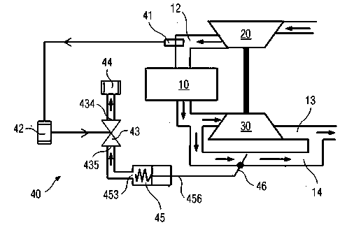
[0030] Such as figure 1 As shown, the engine turbocharger includes a compressor 20, a turbine 30, bypass line 14 and an exhaust gas bleeder. The compressor 20 is connected to the intake pipe 12 of the engine body 10 , and the turbine 30 is connected to the exhaust pipe 13 of the engine body 10 and is coaxial with the compressor 20 . The bypass line 14 communicat...


PUM


Abstract

An engine turbocharger comprises an air compressor (20), a turbine (30), a bypass pipeline (14) and a waste gas exhausting device (40). The waste gas discharge device comprises a pressure sensor (41), an electric control unit (42), a vacuum electromagnetic valve (43), a vacuum pump (44), an exhausting driver (45), and an exhaust valve (46). The pressure sensor is disposed at the downstream part of the air compressor; the electric control unit can receive an output signal from the pressure sensor; the vacuum electromagnetic valve can receive an output signal from the electric control unit; the vacuum electromagnetic valve is provided with a valve outlet and a valve inlet; a pump intake port of the vacuum pump is communicated with the valve outlet of the vacuum electromagnetic valve; the exhausting driver comprises a control end and an operating end; the control end is communicated with the valve inlet of the vacuum electromagnetic valve; the exhaust valve is disposed on the bypass pipeline and can be operated through the operating end. Openness of the exhaust valve is adjusted under electric control according to the pressure of an intake pipe, operating efficiency of the engine turbocharger is improved, and the performance of an engine is improved.

Description

technical field [0001] The invention relates to the technical field of engines, in particular to an exhaust gas release device for an engine turbocharger, especially an engine turbocharger with electronically controlled exhaust gas release control. Background technique [0002] In order to cope with the increasingly stringent energy-saving and emission-reduction regulations around the world, and to improve the overall performance of the engine, turbocharging technology has been widely used and developed. In order to ensure the good performance of the supercharged engine, the combined operating characteristics of the turbine and the compressor are well matched with the engine in a wide range. Therefore, the existing turbochargers are usually equipped with waste gas release valves to To improve the part-load performance of the engine, when the compressor outlet pressure (that is, the engine inlet pressure) reaches a certain level, the bleed valve is automatically opened to byp...

Claims


Application Information

Patent Timeline
IPC IPC(8): F02B37/18
CPCY02T10/12
Inventor 贾和坤尹必峰陈玉炜孙建中何建光徐毅
Owner JIANGSU UNIV
Why Eureka
Try Eureka