
Structural system for controlling transverse response of cable-stayed bridge main beam, auxiliary pier and transition pier

A technology for auxiliary piers and transition piers, applied in the direction of cable-stayed bridges, bridges, bridge parts, etc., can solve the problems of restricting relative movement, safety hazards of main girders, auxiliary piers and transition piers, large lateral displacement and internal force response of cable-stayed bridges, etc. problems, achieve the effects of reducing construction costs, ensuring structural safety and functional requirements, and optimizing lateral structural stiffness and structural damping

Active Publication Date: 2014-08-06
CCCC HIGHWAY CONSULTANTS +1
View PDF4 Cites 8 Cited by
  • Summary
  • Abstract
  • Description
  • Claims
  • Application Information

AI Technical Summary

Problems solved by technology

The transverse wind-resistant support, transverse limit support or limit device are all transverse rigid supports. Under the action of transverse strong winds and earthquakes, the above-mentioned transverse rigid supports often cause the main girder and the tower column of the bridge tower, the main girder and the Collision occurs between the lateral limit support or limit device of the auxiliary pier, the transverse limit support or limit device of the main girder and the transition pier, and restricts the relative movement of the main girder and the bridge tower, auxiliary pier, and transition pier , this kind of rigid restraint system usually makes the lateral displacement and internal force response of the cable-stayed bridge very large, which leads to safety hazards of the main girder, auxiliary piers and transition piers

Method used


Image

  • Structural system for controlling transverse response of cable-stayed bridge main beam, auxiliary pier and transition pier
  • Structural system for controlling transverse response of cable-stayed bridge main beam, auxiliary pier and transition pier
  • Structural system for controlling transverse response of cable-stayed bridge main beam, auxiliary pier and transition pier

Examples


Embodiment Construction

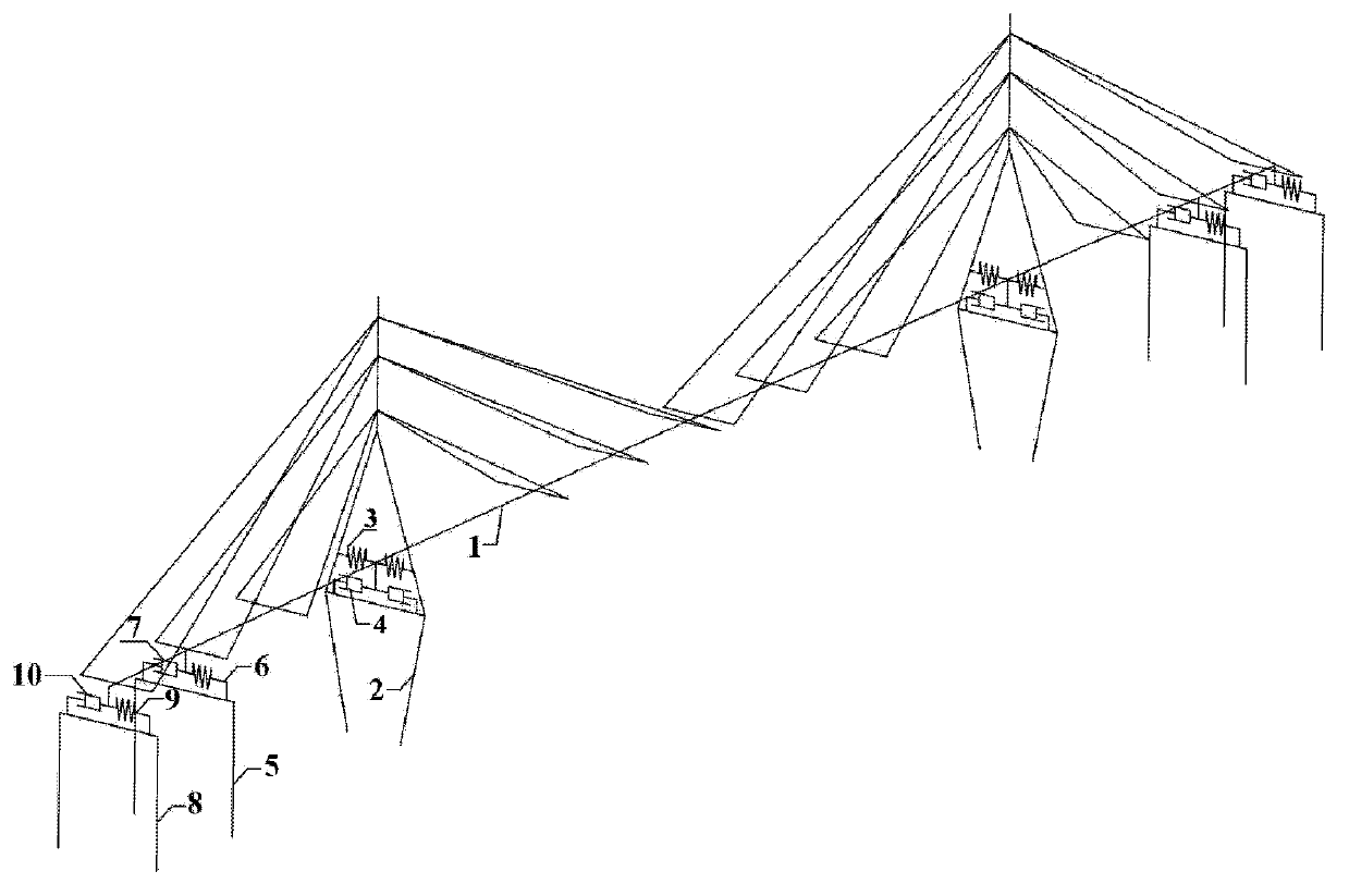
[0028] Such as figure 1 as shown, figure 1 It is a schematic diagram of the structural system for controlling the lateral response of the cable-stayed bridge girder, auxiliary pier and transition pier provided by the present invention. figure 1 The shown cable-stayed bridge has a main girder 1, a bridge tower 2, an auxiliary pier 5 and a transition pier 8, and the structural system for controlling the lateral response of the cable-stayed bridge main girder, auxiliary pier and transition pier includes:

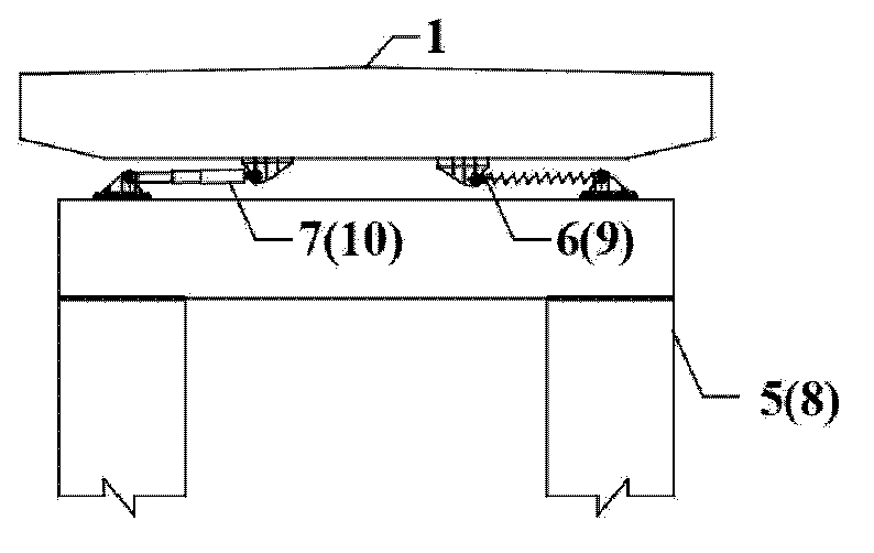
[0029] A plurality of first elastic supports 3 and a plurality of first dynamic damping devices 4 arranged laterally between the main girder 1 and the bridge tower 2; a plurality of second elastic supports 6 arranged laterally between the main girder 1 and the auxiliary pier 5 and a plurality of second dynamic damping devices 7 ; and a plurality of third elastic supports 9 and a plurality of third dynamic damping devices 10 arranged transversely between the main beam 1 and the...


PUM


Abstract

The invention discloses a structural system for controlling transverse response of a cable-stayed bridge main beam, auxiliary piers and transition piers. A cable-stayed bridge comprises a main beam, bridge towers, auxiliary piers and transition piers. The structural system comprises a plurality of transversely arranged first elastic supports and a plurality of first power damping devices among the main beam and the bridge towers, a plurality of transversely arranged second elastic supports and a plurality of second power damping devices among the main beam and the auxiliary piers, and a plurality of transversely arranged third elastic supports and a plurality of third power damping devices among the main beam and the transition piers. The structural system can effectively control transverse displacement and internal force response of the cable-stayed bridge main beam, the auxiliary piers and the transition piers, is simple and reasonable in execution scheme and good in economy, and can be popularized and applied to other bridge types such as suspension bridges.

Description

technical field [0001] The invention relates to the technical field of bridge engineering, in particular to a structural system for controlling the transverse response of a cable-stayed bridge girder, an auxiliary pier and a transition pier. Background technique [0002] Cable-stayed bridge is a modern bridge type with good economy and wide adaptability, and now it has developed into the mainstream bridge type of long-span bridges. The structural system of the cable-stayed bridge is directly related to the overall design, structural safety and function realization of the bridge. The long-span cable-stayed bridge has a soft structure and low damping, and is very sensitive to static and dynamic effects such as automobiles, temperature, strong winds and earthquakes. [0003] A very wide range of research work has been carried out on the structural system of cable-stayed bridges at home and abroad, but most of them focus on the research on the longitudinal structural system and...

Claims


Application Information

Patent Timeline
Patent Type & Authority Applications(China)
IPC IPC(8): E01D11/04E01D19/00
Inventor 张喜刚刘高吴文明李贞新徐源庆冯清海
Owner CCCC HIGHWAY CONSULTANTS
Learn More