
Crankshaft turning and milling machine tool and its tool turret

A tool turret and crankshaft technology, applied to milling machine equipment, milling machine equipment details, other manufacturing equipment/tools, etc., can solve problems such as troubles, achieve the effects of avoiding deflection, improving mobility, and improving machining accuracy

Inactive Publication Date: 2017-04-19
吉迈特车床有限公司
View PDF9 Cites 0 Cited by
  • Summary
  • Abstract
  • Description
  • Claims
  • Application Information

AI Technical Summary

Problems solved by technology

In addition, the known device has the disadvantage that the steady rest described therein is only conditionally suitable for changing workpieces with other dimensions, for example with different distances between the axis of rotation and the connecting rod journal, Because of the cumbersome reassembly of the correcting jaws of the rest rest

Method used


Image

  • Crankshaft turning and milling machine tool and its tool turret
  • Crankshaft turning and milling machine tool and its tool turret
  • Crankshaft turning and milling machine tool and its tool turret

Examples


Embodiment Construction

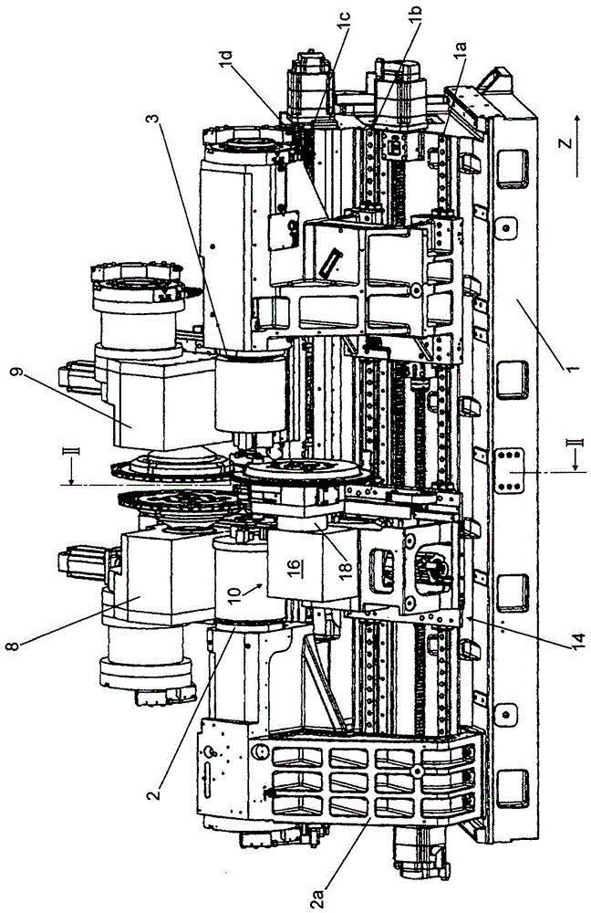
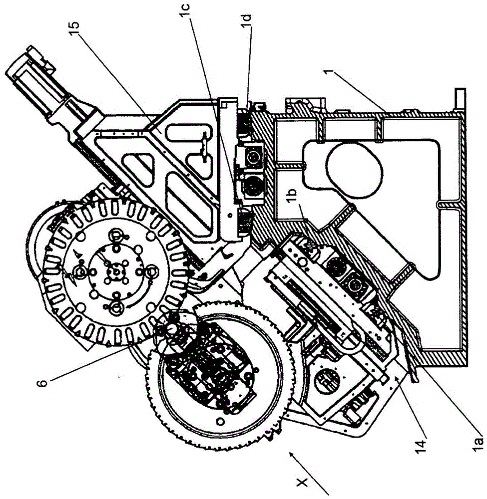
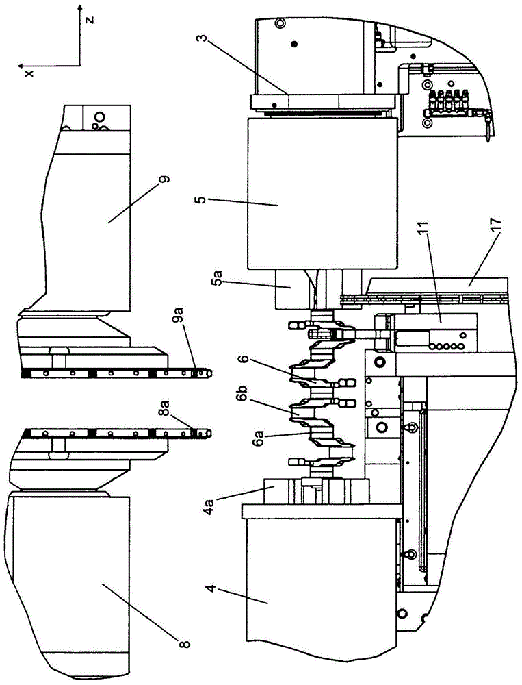
[0023] exist figure 1 The crankshaft turning-milling machine shown in FIG. 1 has a machine tool 1 . The machine tool is provided with lower guides 1a and 1b and upper guides 1c and 1d. On one end of the machine tool 1, a headstock 2a is fixed immovably. The first workpiece spindle 2 is mounted rotatably about its spindle axis in the headstock. The second workpiece spindle 3 is supported displaceably in the direction of the spindle axis on the lower guides 1a, 1b. The two spindle axes are oriented parallel to the direction Z. The workpiece spindle 3 carries an associated chuck 5, and the workpiece spindle 2 carries an associated chuck 4 facing the chuck 5, so that a crankshaft workpiece 6 can be clamped between the chucks 4, 5 (see Figures 2 to 5 ).

[0024] Mounted on the lower guides 1 a , 1 b is an Oldham slide 14 , which is displaceable in the direction Z of the spindle axis and in the direction X transverse to the direction of the spindle axis. The Oldham slide 14 ...


PUM


Abstract

The machine has workpiece spindles (2, 3) comprising respective clamping chucks for clamping end areas of a crankshaft workpiece, where one of the spindles is moved in a spindle axis direction (Z). Milling devices (8, 9) and a turning device (10) are designed such that peripheral surfaces of the end areas, a main bearing and a stroke bearing of the crankshaft workpiece are processed. A bezel is attached to the workpiece and movably supported in the axis direction and in a transverse direction perpendicular to the axis direction. An independent claim is also included for a tool turret.

Description

technical field [0001] The invention relates to a crankshaft turning and milling machine tool and a tool turret for the crankshaft turning and milling machine tool. Background technique [0002] A related device is known from DE 100 52 443 . The crankshaft workpiece is optionally clamped at its ends between centers or in chucks. The corresponding end region of the crankshaft workpiece supported by the center point can be machined by turning or milling in that the jaws of the associated chuck can be moved back so that the tool of the machining unit can reach the end region of the crankshaft workpiece. In order to machine the pin journal of the crankshaft workpiece—for example by milling in which the crankshaft workpiece is rotated at a feed rate about its main axis C—the crankshaft workpiece has to be brought into a defined rotational position . In said document, this is achieved by providing a rotational position stop and a plunger, wherein the plunger is mounted displace...

Claims


Application Information

Patent Timeline
Patent Type & Authority Patents(China)
IPC IPC(8): B23P23/02B23B29/32
CPCB23B5/18B23C3/06B23Q1/76
Inventor C·哈尔姆
Owner 吉迈特车床有限公司
Learn More